Hydraulic System Graphic Symbols
A comprehensive guide to understanding the graphical representation of hydraulic components in a hydrostatic transmission diagram
Introduction to Hydraulic Schematics
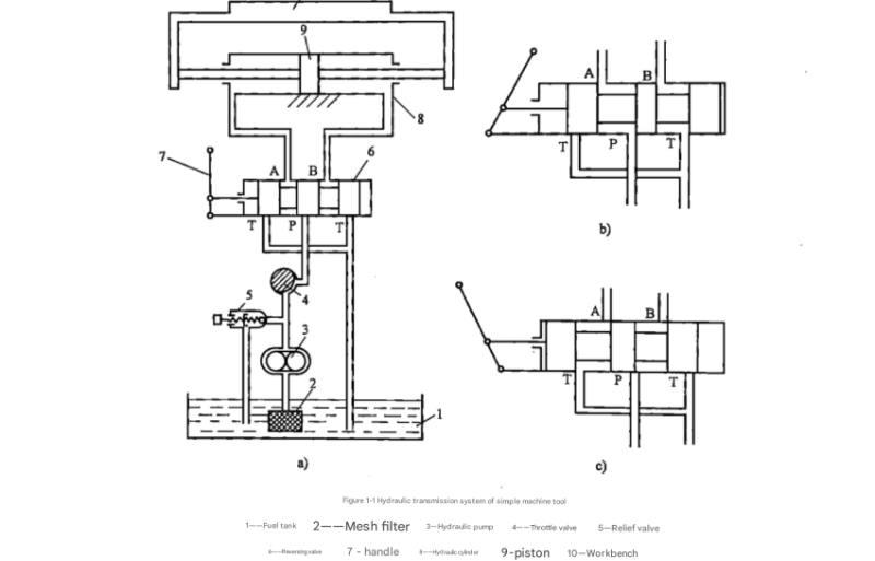
Figure 1-1 shows a semi-structural schematic diagram of a hydraulic transmission system. This type of schematic diagram is highly intuitive and easy to understand but features relatively complex graphics. Drawing becomes particularly inconvenient when there are many components. To simplify the creation of such schematics, each component in the system can be represented using symbols. These symbols indicate only the function of the components, not their structure or parameters. The national standard for hydraulic component function symbols is specified in GB/T786.1-2009, which provides the foundation for creating a clear and consistent hydrostatic transmission diagram.
To facilitate understanding of hydraulic system diagrams represented by function symbols, the following introduces the graphic symbols of hydraulic components appearing in Figure 1-1 (as shown in Figure 1-2) within the context of a hydrostatic transmission diagram. These symbols form the visual language that allows engineers and technicians to interpret and work with hydraulic systems effectively.
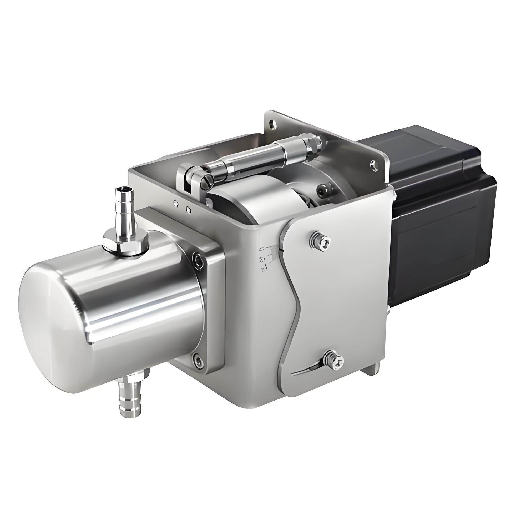
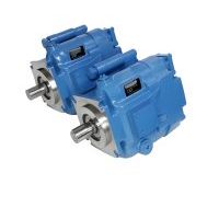
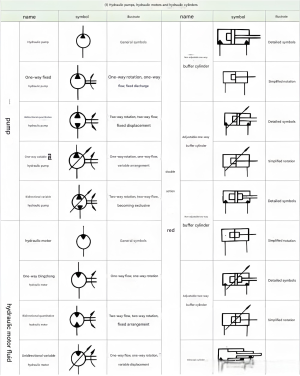
Hydraulic Pump Symbols
The graphic symbol for a hydraulic pump in a hydrostatic transmission diagram consists of a circle with a solid triangle and a rotational direction indicator outside the circle. The tip of the triangle points outward, indicating the direction of oil flow. In the diagram, a unidirectional arrow for rotation indicates one-way rotation, while a bidirectional arrow indicates bidirectional rotation.
In a hydrostatic transmission diagram, a pump without a diagonal arrow穿过 the circle represents a fixed-displacement pump, while one with an arrow represents a variable-displacement pump. This distinction is crucial for understanding the operation and capabilities of the hydraulic system being represented.
The simplicity of these symbols in a hydrostatic transmission diagram belies their importance—they immediately communicate critical information about pump type, flow direction, and operational capabilities to anyone familiar with the standard.
Pump Symbol Variations
Fixed-displacement Pump

Variable-displacement Pump

Unidirectional Rotation
Bidirectional Rotation
Directional Control Valve Symbols
The graphic symbol for a directional control valve in a hydrostatic transmission diagram represents components that change the direction of oil flow. The valve spool must shift positions, typically between 2-3 positions, and valve bodies have different numbers of passages. Based on the number of positions the spool can move to and the number of passages in the valve body, directional control valves are classified as x-position x-port valves.
Understanding these symbols is essential for interpreting the flow control capabilities in any hydrostatic transmission diagram. Each variation provides specific information about how the valve will direct fluid within the system under different operating conditions.
Directional Valve Symbol Interpretation
- Valve positions are represented by squares - the number of squares indicates the number of positions
- Arrows within squares show oil communication paths
- "T" symbols indicate blocked passages
- Symbols outside squares indicate actuation methods
Key Features of Directional Valve Symbols in a Hydrostatic Transmission Diagram
Valve Positions
The working positions of a directional valve are represented by squares in a hydrostatic transmission diagram. The number of squares indicates the number of positions the valve can take.
Flow Paths
Arrow symbols within the squares indicate oil communication in a hydrostatic transmission diagram. The number of intersection points in a square indicates the number of ports in the valve.
Actuation Methods
Symbols outside the squares represent the valve actuation methods in a hydrostatic transmission diagram. Control methods include manual, electric, and hydraulic actuation.
Common Directional Valve Configurations
| Valve Type | Symbol | Description |
|---|---|---|
| 2-position, 2-port | Simple on/off valve commonly used in basic hydrostatic transmission diagram applications | |
| 3-position, 4-port | Versatile valve with neutral position, widely used in directional control for a hydrostatic transmission diagram | |
| 4-position, 3-port | Specialized valve with multiple operating modes for complex hydrostatic transmission diagram requirements |
Pressure Valve Symbols
In a hydrostatic transmission diagram, the square in a pressure valve graphic symbol represents the valve spool. Arrows within the square indicate the oil passages, while the lines on both sides represent the inlet and outlet oil pipes. The dashed lines in the diagram represent control oil paths.
Pressure valves operate on the principle of balancing the hydraulic pressure from the control oil path with the spring force on the other side, a concept clearly communicated through their symbols in a hydrostatic transmission diagram. This balance determines when the valve opens or closes to control system pressure.
Different types of pressure valves—including relief valves, pressure reducing valves, and sequence valves—each have distinct symbols in a hydrostatic transmission diagram, allowing for quick identification of their function within the system.
Pressure Valve Symbol Examples
Pressure Relief Valve
Protects system from overpressure in a hydrostatic transmission diagram
Pressure Valve Operation Principles
All pressure valves in a hydrostatic transmission diagram operate based on force balance principles, but each type serves a specific function:
- Relief Valves: These valves in a hydrostatic transmission diagram open when system pressure exceeds a preset level, diverting fluid back to the reservoir to prevent overpressure damage.
- Pressure Reducing Valves: In a hydrostatic transmission diagram, these maintain a constant reduced pressure in a branch circuit regardless of pressure fluctuations in the main system.
- Sequence Valves: These valves in a hydrostatic transmission diagram control the order of operation of hydraulic actuators by opening only when a preset pressure is reached in the primary circuit.
- Unloading Valves: In a hydrostatic transmission diagram, these reduce pump pressure to a low value when the system doesn't require flow, improving efficiency.
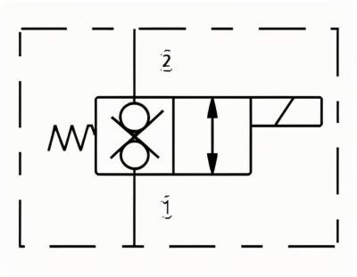
Flow Control Valve Symbols
The flow control valve symbol in a hydrostatic transmission diagram features a gap formed by two arcs, representing the orifice through which oil flows. Oil flow is reduced as it passes through this orifice, creating the flow control function essential in many hydraulic systems.
The arrow in the flow control valve symbol in a hydrostatic transmission diagram indicates that the size of the orifice can be changed, identifying it as an adjustable flow control valve. This adjustability means the flow rate through the valve can be regulated, a critical function in controlling actuator speed in hydraulic systems.
In a hydrostatic transmission diagram, different styles of flow control valve symbols distinguish between fixed and adjustable types, as well as between pressure-compensated and non-compensated varieties, each with specific applications based on system requirements.
Flow Control Valve Variations

Fixed Orifice
Provides constant flow restriction in a hydrostatic transmission diagram
Adjustable Flow Control
Allows manual flow rate adjustment in a hydrostatic transmission diagram
Pressure Compensated
Maintains constant flow despite pressure changes in a hydrostatic transmission diagram
Applications of Flow Control Valves in a Hydrostatic Transmission Diagram
Speed Control
By regulating flow to hydraulic cylinders and motors in a hydrostatic transmission diagram, flow control valves determine the actuation speed of these components, allowing precise control over machine movements.
System Balancing
In multi-actuator systems represented in a hydrostatic transmission diagram, flow control valves distribute fluid appropriately between different circuit branches, preventing unequal operation.
Pressure Regulation
When used in conjunction with pressure valves in a hydrostatic transmission diagram, flow controls help maintain system pressure within desired limits during varying flow conditions.
Energy Conservation
Properly sized flow control valves in a hydrostatic transmission diagram prevent unnecessary fluid movement, reducing energy consumption and heat generation in the system.
Standards and Conventions
In hydraulic system diagrams, including any hydrostatic transmission diagram, there is an important convention: the graphic symbols of hydraulic components should be represented in their static or neutral position. This standardization ensures consistency and clarity across all hydraulic schematics, allowing professionals worldwide to interpret any hydrostatic transmission diagram regardless of its origin.
Following this convention, the semi-structural diagram shown in Figure 1-1 can be converted into the functional symbol-based hydraulic transmission system schematic shown in Figure 1-2. This conversion demonstrates the effectiveness of using standardized symbols in creating a clear, concise hydrostatic transmission diagram that retains all essential functional information while eliminating unnecessary structural details.
GB/T786.1-2009 Key Requirements
The national standard for hydraulic component symbols specifies several important requirements for creating an accurate hydrostatic transmission diagram:
- Symbols represent component functions rather than physical structure
- All symbols must be drawn to scale where necessary for proportional representation in a hydrostatic transmission diagram
- Components are shown in their neutral or de-energized state in a hydrostatic transmission diagram
- Flow direction is indicated by arrows when necessary for clarity in a hydrostatic transmission diagram
- Control methods are clearly indicated for all valves in a hydrostatic transmission diagram
- Connection points are clearly defined to show how components integrate in a hydrostatic transmission diagram
Benefits of Standardized Symbols in a Hydrostatic Transmission Diagram
| Benefit | Description |
|---|---|
| Universal Understanding | A standardized hydrostatic transmission diagram can be interpreted by professionals worldwide regardless of language barriers |
| Simplified Communication | Engineers and technicians can quickly communicate system design and troubleshooting using a hydrostatic transmission diagram |
| Reduced Errors | Standard symbols minimize misinterpretation that could lead to installation or operational errors in a hydrostatic transmission diagram |
| Efficient Documentation | A well-designed hydrostatic transmission diagram provides comprehensive system documentation in a compact format |
| Facilitated Training | Standard symbols make it easier to train new personnel in interpreting and working with a hydrostatic transmission diagram |
Hydraulic Component Symbol Reference
This comprehensive table provides a quick reference for common hydraulic component symbols used in a hydrostatic transmission diagram, following the GB/T786.1-2009 standard.
| Component Category | Component Name | Symbol | Symbol Meaning in Hydrostatic Transmission Diagram |
|---|---|---|---|
| Pumps & Motors | Fixed-displacement Pump |  |
Constant flow output in a hydrostatic transmission diagram |
| Variable-displacement Pump |  |
Adjustable flow output in a hydrostatic transmission diagram | |
| Hydraulic Motor |  |
Converts hydraulic energy to mechanical rotation in a hydrostatic transmission diagram | |
| Valves | 2/2 Directional Valve |  |
Two-position, two-port flow control in a hydrostatic transmission diagram |
| Pressure Relief Valve |  |
Protects system from overpressure in a hydrostatic transmission diagram | |
| Adjustable Flow Control |  |
Regulates fluid flow rate in a hydrostatic transmission diagram | |
| Actuators & Accessories | Double-acting Cylinder |  |
Produces force in both directions in a hydrostatic transmission diagram |
| Reservoir |  |
Stores hydraulic fluid in a hydrostatic transmission diagram | |
| Filter |  |
Removes contaminants from fluid in a hydrostatic transmission diagram |
Understanding the Language of Hydraulics
Mastering the graphic symbols used in a hydrostatic transmission diagram is essential for anyone working with hydraulic systems. These symbols form a universal language that allows engineers, technicians, and operators to understand system design, troubleshoot problems, and communicate effectively about hydraulic systems regardless of their complexity.
By following the GB/T786.1-2009 standard, professionals ensure that their hydrostatic transmission diagram documentation is clear, consistent, and understandable to others in the field. This standardization promotes safety, efficiency, and accuracy in the design, installation, operation, and maintenance of hydraulic systems.