Hydraulic Shock and Cavitation Phenomena
Understanding the critical phenomena that affect hydraulic systems and how to mitigate their adverse effects on performance and longevity.
In hydraulic transmission systems, both hydraulic shock and cavitation can adversely affect the normal operation of the system. Therefore, it is necessary to understand the causes of these phenomena and take measures to prevent and control them. The behavior of hydraulic transmission fluid under various conditions plays a crucial role in these phenomena, making its proper selection and maintenance essential for system reliability.
This comprehensive guide explores the mechanisms behind hydraulic shock and cavitation, their detrimental effects, calculation methods for pressure transients, and effective prevention strategies. Understanding these aspects helps engineers design more robust systems and maintain optimal performance of hydraulic machinery.
Hydraulic Shock
In a hydraulic system, when the pressure rises suddenly to a very high peak in an instant due to certain reasons, this phenomenon is called hydraulic shock. The dynamics of hydraulic transmission fluid during these pressure spikes can significantly impact system integrity and performance.
Figure 1: Pressure spike visualization during hydraulic shock event
1. Causes and Hazards of Hydraulic Shock
In situations such as sudden closure of a valve or rapid braking of a hydraulic cylinder, the flow of hydraulic transmission fluid in the system is suddenly blocked. Due to the inertial effect of the fluid flow, starting from the blocked end, the fluid rapidly converts kinetic energy into pressure energy layer by layer, thus generating a pressure shock wave.
Afterwards, starting from the other end, the pressure energy is converted back into kinetic energy layer by layer, and the fluid flows in the reverse direction. Then, the kinetic energy is converted into pressure energy again, and this energy conversion repeats. Due to the rapid reciprocating propagation of this pressure wave, pressure oscillation is formed in the system.
In reality, due to the frictional force of the hydraulic transmission fluid and the elastic effect of the fluid and pipe walls, energy is continuously consumed, which causes the oscillation process to gradually attenuate and stabilize.
Key Hazards:
- Instantaneous pressure peaks can be several times higher than normal operating pressure
- Damage to sealing devices, pipes, or hydraulic components
- Equipment vibration and excessive noise generation
- Misoperation of hydraulic components such as pressure relays and sequence valves
- Accelerated degradation of hydraulic transmission fluid due to excessive pressure and temperature
- Reduced system efficiency and potential for catastrophic failure
2. Shock Pressure Calculation
Assuming the normal working pressure of the system is p, the maximum pressure when hydraulic shock occurs, i.e., the peak pressure of the first pressure shock wave, is:
Pmax = p + Δp
(Equation 2-45)
Where Δp is the maximum increase in shock pressure. Because hydraulic shock is an unsteady flow with a very complex dynamic process and many influencing factors, it is difficult to accurately calculate the value of Δp. The following section introduces approximate calculation formulas for Δp under two hydraulic shock conditions.
(1) Hydraulic shock when pipeline valves close
Let the cross-sectional area of the pipeline be A, the length of the pipeline where the shock occurs be l, the time for the first pressure shock wave to propagate within length l be t, the density of the hydraulic transmission fluid be ρ, the flow velocity of the fluid in the pipe be v, and the flow velocity after the valve is closed be zero. From the momentum equation:
ΔpA = ρA lv/t
Δp = ρ lv/t = ρ cv
(Equation 2-46)
Where c is the propagation speed of the pressure shock wave in the pipe, c = l/t. When applying Equation (2-46), it is necessary to know the value of c, which is related not only to the bulk modulus K of the hydraulic transmission fluid but also to the elastic modulus E of the pipe material, the inner diameter d of the pipe, and the wall thickness δ. Therefore, the calculation formula for c is:
c = √(K/ρ) / √[1 + (dE)/(δK)]
(Equation 2-48)
In hydraulic transmission, the value of c is generally between 900~1400m/s. If the flow velocity v does not suddenly drop to zero but to v₁, then Equation (2-46) can be written as:
Δp = ρc(v - v₁)
(Equation 2-47)
Let the time for the pressure shock wave to reciprocate once in the pipe be t₀ = 2l/c. When the valve closing time t < t₀, the pressure peak is large, which is called direct shock. Its Δp value can be calculated according to Equation (2-46) or Equation (2-48). When t > t₀, the pressure peak is smaller, which is called indirect shock. At this time, the calculation formula for Δp is:
Δp = ρc(v - v₁)t₀/t
(Equation 2-49)
(2) Hydraulic shock during braking of moving parts
Assume that the total mass of the moving part is m, the deceleration time during braking is Δt, the velocity reduction value is Δv, and the effective area of the hydraulic cylinder is A. According to the momentum theorem:
Δp = (mΔv)/(AΔt)
(Equation 2-50)
In Equation (2-50), factors such as damping and leakage are ignored, so the calculation result is larger but safer. The properties of the hydraulic transmission fluid, particularly its viscosity and compressibility, can influence these calculations and should be considered for precise system design.
3. Measures to Reduce Hydraulic Shock
Analyzing the influencing factors of Δp in Equations (2-49) and (2-50), the main measures to reduce hydraulic shock can be summarized as follows:
Extend Operation Time
Prolong the valve closing time and the braking and reversing time of moving parts. Practice has proved that if the braking and reversing time of moving parts can be greater than 0.2s, the impact will be greatly reduced. In hydraulic systems, directional valves with adjustable reversing time can be used to achieve this, allowing the hydraulic transmission fluid to adjust more gradually.
Limit Velocities
Restrict pipeline flow velocity and moving part speed. For example, in machine tool hydraulic systems, the pipeline flow velocity is usually limited to below 4.5m/s, and the speed of moving parts driven by hydraulic cylinders should generally not exceed 10m/min, which helps control the kinetic energy of the hydraulic transmission fluid.
Optimize Pipeline Design
Appropriately increase the pipe diameter and try to shorten the pipe length. Increasing the pipe diameter can not only reduce the flow velocity but also reduce the pressure shock wave velocity c value. The purpose of shortening the pipe length is to reduce the propagation time of the pressure shock wave. If necessary, accumulators and other buffer devices can be installed near the impact area to achieve this, helping to stabilize hydraulic transmission fluid flow.
Use Flexible Hoses
Employ flexible hoses to increase the elasticity of the system. The flexibility of these hoses can absorb some of the shock energy and reduce the propagation of pressure waves through the hydraulic transmission fluid, thereby mitigating the effects of hydraulic shock.
Figure 2: Effectiveness of various hydraulic shock mitigation strategies
Cavitation Phenomena
In a hydraulic system, if the pressure at a certain point is lower than the air separation pressure, the air originally dissolved in the hydraulic transmission fluid will separate out, leading to the phenomenon of a large number of bubbles in the fluid, which is called cavitation.
If the pressure in the fluid further decreases to the saturated vapor pressure, the fluid will vaporize rapidly, producing a large number of vapor bubbles, and the cavitation phenomenon will be more serious at this time. The presence of these bubbles fundamentally changes the behavior of the hydraulic transmission fluid, affecting both system performance and component longevity.
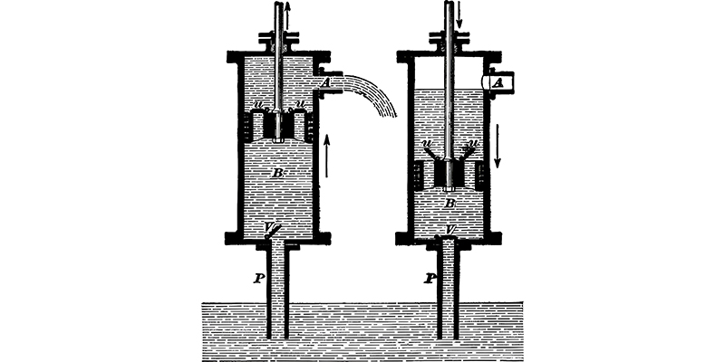
Figure 3: Cavitation bubble formation in hydraulic transmission fluid under low pressure conditions
Effects of Cavitation
When cavitation occurs in a hydraulic system, a large number of bubbles destroy the continuity of the hydraulic transmission fluid flow, causing flow and pressure pulsations. When bubbles enter the high-pressure area with the fluid flow, they collapse rapidly, leading to local hydraulic shock, noise, and vibration.
When bubbles attached to metal surfaces collapse, the local high temperature and pressure they generate can cause metal erosion. This corrosive effect caused by cavitation is called cavitation erosion. Cavitation erosion can deteriorate the working performance of hydraulic components and greatly shorten their service life.
Primary Consequences of Cavitation:
- Flow and pressure pulsations reducing system efficiency
- Noise and vibration affecting system performance and operator comfort
- Metal erosion (cavitation erosion) on component surfaces
- Reduced service life of hydraulic components
- Potential for system blockages when bubbles collapse
- Degradation of hydraulic transmission fluid due to localized high temperatures
- Increased maintenance costs and downtime
Common Locations for Cavitation
Cavitation mostly occurs at valve ports and pump inlets. Due to the narrow passage of the valve port, the flow velocity of the hydraulic transmission fluid increases, and the pressure drops significantly, leading to cavitation.
Cavitation can also occur when the installation height of the pump is too large, the diameter of the suction pipe is too small, the suction resistance is too large, or the pump speed is too high, resulting in excessive vacuum at the inlet.
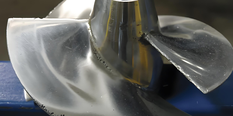
Figure 4: Cross-section showing typical cavitation areas in a hydraulic pump
Measures to Reduce Cavitation and Cavitation Erosion
To reduce the harm of cavitation and cavitation erosion, the following measures are usually taken, many of which focus on maintaining proper pressure and flow characteristics of the hydraulic transmission fluid:
Reduce Pressure Drop
Minimize the pressure drop across orifices or gaps. Generally, it is desirable that the pressure ratio before and after the orifice or gap p₁/p₂ < 3.5. This helps maintain adequate pressure in the hydraulic transmission fluid to prevent the formation of vapor bubbles.
Optimize Suction Line Design
Reduce the pump suction height, appropriately increase the diameter of the suction pipe, limit the flow velocity of the hydraulic transmission fluid in the suction pipe, and minimize pressure losses in the suction pipe (such as timely cleaning the filter or replacing the filter element). For pumps with poor self-priming capability, an auxiliary pump should be used for oil supply. These measures help maintain sufficient pressure at the pump inlet to prevent cavitation.
Ensure Proper Sealing
The pipeline must be well sealed to prevent air from entering the system. Even small amounts of air can significantly lower the pressure at which cavitation occurs in the hydraulic transmission fluid, increasing the likelihood and severity of cavitation damage.
Use Proper Hydraulic Transmission Fluid
Select a hydraulic transmission fluid with appropriate viscosity and lubricating properties. High-quality hydraulic transmission fluid is formulated to resist foaming and maintain stable properties under varying pressure and temperature conditions, helping to minimize cavitation effects. Regular fluid analysis and replacement are also essential to maintain optimal performance.
Conclusion
Both hydraulic shock and cavitation represent significant challenges in hydraulic system design and operation. Understanding the underlying mechanisms, recognizing the conditions that promote these phenomena, and implementing appropriate preventive measures are essential for maintaining system performance, reliability, and longevity. The proper selection and maintenance of hydraulic transmission fluid play a critical role in mitigating these issues and ensuring optimal system operation.
Learn more