Hydraulic Servo Overview
A Hydraulic servo system is a sophisticated control system that uses hydraulic fluid power—an area linked to clarifying what is hydrostatic transmission—to achieve precise positioning, velocity, or force control. These systems combine the power density of hydraulics with the precision of electronic control, making them indispensable in applications requiring both high force and exact movement.
The fundamental principle behind a Hydraulic servo system involves the use of a feedback loop to continuously compare the actual system output with the desired output. Any discrepancy between these values generates an error signal, which is then used to adjust the hydraulic power output, correcting the system behavior.
The history of Hydraulic servo technology dates back to the early 20th century, with significant advancements during World War II for aircraft control systems. Post-war developments saw these systems adopted across various industries, from manufacturing machinery to aerospace applications.
Key advantages of Hydraulic servo systems include their exceptional power-to-weight ratio, high stiffness, rapid response times, and ability to maintain precise control under varying load conditions. These characteristics make them ideal for applications ranging from flight simulators and industrial robots to metal forming machinery and material testing equipment.
Modern Hydraulic servo systems integrate advanced electronics, sensors, and software algorithms to achieve unprecedented levels of precision and efficiency. These intelligent systems can adapt to changing operating conditions, self-diagnose faults, and communicate with other automation systems, making them a cornerstone of Industry 4.0 initiatives.
Understanding the basic components of a Hydraulic servo system is essential for appreciating its operation. These typically include a hydraulic power supply (pump, reservoir, and filters), servo control elements (valves or pumps), actuation devices (cylinders or motors), sensors for feedback, and a controller that processes the error signal and generates appropriate commands.
The performance of a Hydraulic servo system is evaluated based on several key parameters: bandwidth (frequency response), accuracy, repeatability, resolution, and dynamic response. These factors determine the system's suitability for specific applications, with high-performance systems required for demanding tasks like missile guidance or precision machining.
Hydraulic Servo System Fundamentals
Basic components of a Hydraulic servo system
Working Principle
Closed-loop control system using hydraulic power for precise actuation
Response Time
Microsecond to millisecond range depending on system design
Power Capability
From fractional horsepower to thousands of kilowatts Optical Transceiver.
Key Performance Metrics of Hydraulic Servo Systems
Typical Hydraulic Servo Control Components
A Hydraulic servo system comprises several key components working in harmony to achieve precise control. Each component plays a critical role in converting electrical signals into controlled mechanical motion through hydraulic power, with distinctions like hydraulic oil vs transmission fluid influencing system performance..
At the heart of any Hydraulic servo system is the power supply unit, which typically includes an electric motor driving a hydraulic pump, a reservoir to store hydraulic fluid, filters to maintain fluid cleanliness, and a pressure relief valve to protect the system from overpressure conditions. The pump delivers a continuous flow of hydraulic fluid at a specified pressure, serving as the system's power source.
Servo valves represent the primary control element in most Hydraulic servo systems. These precision devices modulate fluid flow rate and direction in response to electrical input signals, acting as the interface between the electronic control system and hydraulic power. Servo valves are characterized by their high sensitivity, fast response, and precise flow control capabilities.
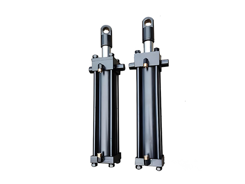
Actuators convert hydraulic energy into mechanical motion and come in two primary forms: linear actuators (hydraulic cylinders) and rotary actuators (hydraulic motors). Hydraulic cylinders produce linear motion through the extension and retraction of a piston rod, while hydraulic motors generate rotational motion. Both types offer high force/torque output and precise positioning capabilities essential for Hydraulic servo applications.
Feedback sensors provide the critical information needed for closed-loop control in a Hydraulic servo system. Position sensors (such as linear variable differential transformers, potentiometers, or optical encoders) measure the actual position of the actuator, while pressure sensors monitor system pressures. These sensors generate electrical signals proportional to the measured parameters, which are fed back to the controller.
The controller serves as the "brain" of the Hydraulic servo system, processing the feedback signals and comparing them with the desired setpoint. Using various control algorithms (typically proportional-integral-derivative or PID control), the controller calculates the appropriate correction signal and sends it to the servo valve, adjusting the hydraulic output to minimize any error between the desired and actual positions.
Auxiliary components such as accumulators, manifolds, hoses, and fittings complete the Hydraulic servo system. Accumulators store hydraulic energy to meet peak demand, reduce pressure fluctuations, and provide emergency power in case of primary power failure. Manifolds simplify fluid distribution, while high-pressure hoses and fittings connect the various components, ensuring reliable fluid transfer throughout the system.
The selection of appropriate components for a Hydraulic servo system depends on specific application requirements, including load capacity, speed, precision, environmental conditions, and duty cycle. Proper component sizing and selection are critical to achieving optimal system performance, efficiency, and reliability.
Hydraulic Servo Components
Hydraulic Pumps
Provide pressurized fluid flow for system operation
Servo Valves
Precision flow control in response to electrical signals
Actuators
Convert hydraulic energy to mechanical motion
Sensors
Provide feedback for closed-loop control
Component Selection Criteria
- Operating pressure and flow requirements
- Response time and bandwidth needs
- Environmental conditions (temperature, contaminants)
- Precision and accuracy specifications
- Reliability and maintenance requirements
- Power-to-weight and size constraints
Electro-Hydraulic Servo Valves
Electro-hydraulic servo valves are critical components in modern Hydraulic servo systems, serving as the interface between electrical control signals and hydraulic power. These precision devices convert low-power electrical signals into precise control of hydraulic fluid flow—with considerations like transmission oil vs fluid influencing system performance—enabling accurate positioning, velocity, and force control in various industrial applications.
The basic operation of an electro-hydraulic servo valve involves a torque motor or voice coil that converts the electrical input signal into a mechanical force or displacement. This mechanical motion acts upon a spool or flapper, which modulates the flow of hydraulic fluid through the valve ports, directing fluid to or from the hydraulic actuator in a Hydraulic servo system.
There are several types of electro-hydraulic servo valves, each with unique characteristics suited to specific Hydraulic servo applications. Two-stage servo valves, the most common type, feature a small pilot stage that controls a larger main stage, providing high flow rates with excellent dynamic response. Direct drive servo valves eliminate the pilot stage, offering improved reliability and reduced sensitivity to fluid contamination.
Key performance parameters for electro-hydraulic servo valves include flow gain (relationship between input signal and output flow), pressure gain (relationship between input signal and pressure drop across the actuator), null bias (flow at zero input signal), and frequency response (ability to follow rapid signal changes). These parameters determine the valve's suitability for different Hydraulic servo system requirements.
The design of electro-hydraulic servo valves incorporates several advanced features to ensure optimal performance in Hydraulic servo systems. These include feedback mechanisms (either mechanical or electrical) that provide position feedback of the spool or flapper, ensuring precise control and stability. Many modern valves also include built-in electronics for signal conditioning, diagnostics, and communication with system controllers.
Proper maintenance of electro-hydraulic servo valves is essential for maintaining the performance of Hydraulic servo systems. This includes maintaining clean hydraulic fluid with appropriate filtration (typically 3-5 micrometers), monitoring fluid temperature and viscosity, and following recommended service intervals. Contamination is the primary cause of servo valve failure, as even small particles can damage the precision mating surfaces.
Recent advancements in electro-hydraulic servo valve technology have focused on improving efficiency, reducing energy consumption, and enhancing durability in Hydraulic servo systems. These include the development of proportional servo valves that offer improved efficiency for certain applications, as well as smart valves with integrated sensors and communication capabilities for condition monitoring and predictive maintenance.
The selection of the appropriate electro-hydraulic servo valve for a Hydraulic servo system depends on factors such as required flow rate, operating pressure, response time, control accuracy, environmental conditions, and fluid compatibility. Proper valve sizing and selection are critical to achieving the desired system performance while ensuring reliability and efficiency.
Electro-Hydraulic Servo Valve Technology
Servo Valve Types Comparison
| Valve Type | Response | Flow Capacity | Reliability | Cost |
|---|---|---|---|---|
| Two-Stage Servo | Excellent | High | Good | High |
| Direct Drive | Very Good | Medium | Excellent | Very High |
| Proportional Servo | Good | High | Very Good | Medium |
Key Servo Valve Specifications
- Maximum Operating Pressure: 350-420 bar
- Flow Capacity: 0.5-500 l/min
- Frequency Response: 50-300 Hz
- Input Signal: ±10V, 4-20mA
- Operating Temperature: -20°C to +70°C
Hydraulic Servo System Examples
Hydraulic servo systems find application across a wide range of industries, leveraging their unique combination of high power density, precise control, and rapid response—with proper transmission fluid for hydraulic fluid selection underpinning these performance advantages. These real-world implementations demonstrate the versatility and performance capabilities of Hydraulic servo technology in solving complex engineering challenges.
In the aerospace industry, Hydraulic servo systems are critical for flight control surfaces such as ailerons, elevators, and rudders. These systems must provide precise positioning under varying aerodynamic loads while ensuring fail-safe operation. Modern aircraft typically use redundant Hydraulic servo systems to enhance reliability, with each control surface often powered by multiple independent hydraulic circuits.
Industrial manufacturing relies heavily on Hydraulic servo systems for precision machining operations. Computer Numerical Control (CNC) machine tools utilize these systems to position cutting tools with micron-level accuracy, enabling the production of complex components with tight tolerances. The high stiffness of Hydraulic servo systems minimizes deflection under cutting forces, ensuring consistent part quality even during heavy machining operations.
Simulation technology represents another important application area for Hydraulic servo systems. Flight simulators, driving simulators, and training devices use these systems to replicate realistic motion, providing immersive training environments. These motion platforms typically employ six-degree-of-freedom (6DoF) Hydraulic servo systems that can precisely control position, velocity, and acceleration to simulate various conditions and scenarios.
In the energy sector, Hydraulic servo systems play a vital role in power generation equipment. Gas and steam turbines use servo-controlled valves to regulate fuel flow and steam pressure, maintaining stable operation across varying load conditions. Wind turbines employ Hydraulic servo systems to adjust blade pitch, optimizing energy capture and protecting the turbine during high wind conditions.
Material testing machines rely on Hydraulic servo systems to apply controlled forces and displacements to test specimens. These systems can perform tension, compression, bending, and fatigue tests with precise control over load, displacement, or strain. The ability to program complex test profiles and maintain precise control throughout the test makes Hydraulic servo technology indispensable in materials science and engineering.
Mobile equipment, such as construction machinery and agricultural vehicles, increasingly incorporates Hydraulic servo systems for improved performance and operator control. These systems enable precise control of attachments like excavator buckets, crane booms, and agricultural implements, enhancing productivity while reducing operator fatigue. Modern mobile Hydraulic servo systems often integrate with electronic control systems for automated operations and telematics.
Research and development facilities utilize specialized Hydraulic servo systems for various experimental applications. These range from earthquake simulation tables that test structural responses to controlled vibrations, to high-speed material processing systems that require precise synchronization of multiple axes. The adaptability of Hydraulic servo technology makes it suitable for these unique and often demanding research environments.
As industries continue to demand higher performance, greater efficiency, and improved precision, the application of Hydraulic servo systems continues to expand. Integration with advanced control algorithms, IoT connectivity, and artificial intelligence is opening new possibilities for adaptive, self-optimizing Hydraulic servo systems that can continuously improve performance while reducing energy consumption and maintenance requirements.Electronic shelf labels.
Aerospace Applications
Flight control systems requiring precise positioning under extreme conditions
Manufacturing Systems
Precision machining and automation with micron-level positioning capabilities
Simulation Technology
Motion platforms providing realistic training environments with 6DoF capabilities
Emerging Applications
- Renewable energy systems requiring precise control
- Autonomous vehicle test platforms and robotics
- Medical equipment with force-controlled mechanisms
- Smart infrastructure monitoring and control systems
Industry Adoption of Hydraulic Servo Technology
Interested in Hydraulic Servo Solutions?
Our team of experts can help design, implement, and optimize hydraulic servo systems for your specific application requirements. Related Lithium Battery Manufacturing.
Contact Our Specialists