Hydraulic systems play a critical role in modern engineering, powering everything from heavy machinery to precision industrial equipment. At the core of these systems lies the Hydraulic fluid, a specially formulated substance that enables the transfer of power through pressure. Understanding the properties and behavior of Hydraulic fluid is essential for designing, operating, and maintaining efficient hydraulic systems.
This comprehensive guide explores the fundamental principles of hydraulic fluid mechanics, covering the physical properties of liquids, static and dynamic behavior, pressure losses, flow characteristics through various components, and important phenomena like hydraulic shock and cavitation. Each section builds upon the previous one to provide a complete understanding of how Hydraulic fluid enables the efficient operation of hydraulic systems.
Physical Properties of Liquids
The behavior of is hydraulic fluid the same as hydraulic oil in hydraulic systems is largely determined by its physical properties. These properties dictate how the fluid will respond to changes in temperature, pressure, and flow conditions, ultimately affecting system performance, efficiency, and longevity.
Density (ρ) is a fundamental property representing mass per unit volume. For Hydraulic fluid, density typically ranges between 850-950 kg/m³ at 15°C. It varies slightly with temperature, decreasing as temperature increases due to thermal expansion. This property is crucial for calculating pressure head and buoyancy effects in hydraulic systems.
Specific weight (γ) is the weight per unit volume, calculated as the product of density and gravitational acceleration (γ = ρg). This property is particularly important in static systems where fluid weight contributes to pressure differences.
Viscosity is perhaps the most critical property of Hydraulic fluid, representing its resistance to flow. Dynamic viscosity (μ) measures the internal friction between fluid layers, while kinematic viscosity (ν) is the ratio of dynamic viscosity to density (ν = μ/ρ). Viscosity index (VI) indicates how much a fluid's viscosity changes with temperature—higher VI values mean less variation, which is desirable for consistent Hydraulic fluid performance across operating temperatures.
Compressibility is the measure of a fluid's volume change under pressure. While liquids are relatively incompressible compared to gases, Hydraulic fluid does compress slightly (typically 0.5-1% per 1000 psi). This property becomes important in systems requiring precise control and can affect response times in hydraulic circuits.
Other important properties include:
- Pour point: The lowest temperature at which Hydraulic fluid will flow
- Flash point: The temperature at which vapors ignite in the presence of an ignition source
- Fire point: The temperature at which the fluid will sustain combustion
- Oxidation stability: Resistance to chemical breakdown when exposed to oxygen
- Demulsibility: Ability to separate from water contamination
- Anti-wear properties: Additives that protect system components from wear
Proper selection of Hydraulic fluid based on these properties is essential for system efficiency, component life, and overall performance. Operating conditions, including temperature range, pressure levels, and system requirements, must all be considered when choosing the appropriate Hydraulic fluid.
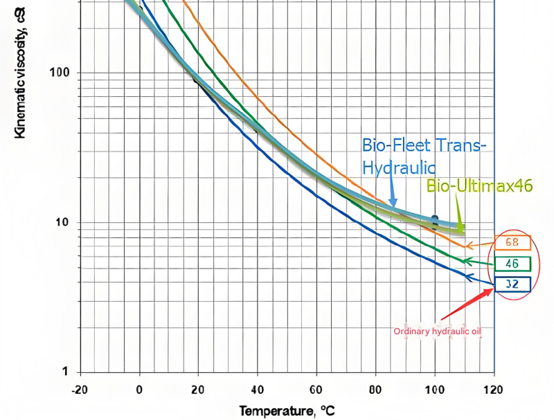
Viscosity Characteristics of Hydraulic Fluid
Viscosity changes significantly with temperature, affecting Hydraulic fluid performance in different operating conditions.
Key Properties of Hydraulic Fluid
Fundamentals of Fluid Statics
Fluid statics deals with the behavior of stationary fluids, including Hydraulic fluid, and the forces exerted on submerged surfaces. Understanding these principles is essential for designing hydraulic system components like reservoirs, tanks, and pressure vessels.Hydrostatic。
Pressure (p) in a static fluid is defined as force per unit area. In a stationary Hydraulic fluid, pressure increases with depth due to the weight of the fluid above. The pressure at any point in a static fluid can be calculated using the hydrostatic equation: p = p₀ + γh, where p₀ is the pressure at the reference point, γ is the specific weight of the Hydraulic fluid, and h is the vertical distance from the reference point.
Pascal's Law is fundamental to hydraulic systems, stating that pressure applied to an enclosed fluid is transmitted undiminished to every portion of the fluid and the walls of its container. This principle enables force multiplication in hydraulic systems: a small force applied to a small piston creates pressure that generates a larger force on a larger piston. Mathematically, this relationship is expressed as F₁/A₁ = F₂/A₂, where F is force and A is piston area.
Pressure in static Hydraulic fluid has several important characteristics:
- Pressure acts equally in all directions at a point (isotropic)
- Pressure is the same at all points on the same horizontal plane in a connected body of the same fluid
- Pressure varies linearly with vertical distance in a homogeneous fluid
- Pressure changes are transmitted instantaneously throughout a static fluid
Forces on submerged surfaces in Hydraulic fluid can be categorized as:
- Forces on plane surfaces: Calculated by determining the resultant pressure force and its point of application (center of pressure)
- Forces on curved surfaces: Resolved into horizontal and vertical components for easier calculation
In hydraulic system design, these principles are applied to determine tank dimensions, calculate wall thicknesses, design pressure relief systems, and ensure proper operation of components like accumulators that rely on static pressure principles. Understanding fluid statics also helps in troubleshooting issues like air pockets in Hydraulic fluid, which can disrupt pressure transmission and system performance.
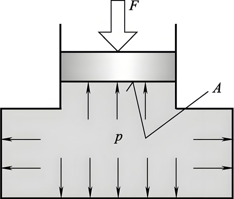
Pascal's Law in Hydraulic Systems
Pressure applied to Hydraulic fluid is transmitted equally throughout the system, enabling force multiplication.
Hydrostatic Pressure Distribution
Fundamentals of Fluid Dynamics
Fluid dynamics examines the behavior of moving fluids, including Hydraulic fluid, and the forces that produce such motion. This branch of fluid mechanics is crucial for understanding how Hydraulic fluid flows through pipes, valves, and other components in hydraulic systems.hydraulic drive system.
The continuity equation is a fundamental principle based on the conservation of mass. For incompressible fluids like Hydraulic fluid, it states that the mass flow rate is constant throughout a flow system. Mathematically, this is expressed as Q = A₁v₁ = A₂v₂, where Q is the volumetric flow rate, A is the cross-sectional area, and v is the fluid velocity at different points in the system. This principle explains why fluid velocity increases when flowing through smaller passages and decreases in larger ones.
Bernoulli's equation, based on the conservation of energy, is another cornerstone of fluid dynamics. It relates pressure, velocity, and elevation in a flowing fluid. For steady, incompressible flow of Hydraulic fluid with negligible friction, the equation states: p/γ + v²/(2g) + z = constant, where p is pressure, γ is specific weight, v is velocity, g is gravitational acceleration, and z is elevation. This equation helps analyze energy transformations in hydraulic systems, such as how pressure energy converts to kinetic energy in nozzles or how velocity pressure converts back to static pressure in diffusers.
Flow characteristics of Hydraulic fluid are categorized based on their behavior:
- Steady vs. unsteady flow: Flow parameters (velocity, pressure) are constant vs. changing with time
- Uniform vs. non-uniform flow: Velocity profile is constant vs. changing along the flow path
- Laminar vs. turbulent flow: Fluid moves in parallel layers with no mixing vs. chaotic motion with significant mixing
The Reynolds number (Re) is a dimensionless parameter that predicts flow regime transitions. It's calculated as Re = (ρvd)/μ, where ρ is density, v is velocity, d is characteristic dimension (e.g., pipe diameter), and μ is dynamic viscosity. For Hydraulic fluid in pipes, laminar flow typically occurs below Re = 2000, while turbulent flow occurs above Re = 4000, with a transitional range in between.
Momentum equations, based on Newton's second law, analyze the forces exerted by flowing Hydraulic fluid on system components. These equations are essential for designing pipe supports, calculating forces on valves, and determining the reactions needed to stabilize hydraulic system components during operation.
Understanding these dynamic principles allows engineers to optimize Hydraulic fluid flow paths, minimize energy losses, predict pressure drops, and design efficient hydraulic components that work harmoniously with the properties of the selected Hydraulic fluid.
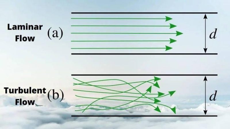
Laminar vs. Turbulent Flow in Hydraulic Fluid
Flow regime significantly affects pressure losses and heat generation in hydraulic systems.
Bernoulli's Principle Demonstration
Pressure Losses in Fluid Flow
When Hydraulic fluid flows through pipes, hoses, and components, energy is lost due to friction, resulting in pressure drops. These pressure losses are unavoidable but can be minimized through proper system design. Understanding and calculating these losses is essential for ensuring adequate pressure at all points in a hydraulic system.
Major losses occur due to friction between the Hydraulic fluid and the walls of straight pipes, as well as internal friction within the fluid itself. For laminar flow, the Darcy-Weisbach equation simplifies to the Hagen-Poiseuille equation: Δp = (32μLv)/(d²), where Δp is pressure drop, μ is dynamic viscosity, L is pipe length, v is fluid velocity, and d is pipe diameter. This shows that laminar pressure losses are directly proportional to the viscosity of the Hydraulic fluid and flow velocity.hydraulic fluid tractor.
For turbulent flow, the Darcy-Weisbach equation is used: Δp = f(L/d)(ρv²/2), where f is the friction factor. The friction factor depends on the Reynolds number and pipe roughness. For smooth pipes, the friction factor decreases with increasing Reynolds number but eventually becomes constant in the fully turbulent region. For rough pipes, the friction factor becomes independent of Reynolds number at high values, depending only on relative roughness.
Minor losses occur in fittings, valves, bends, elbows, tees, and other components that disrupt the flow pattern of Hydraulic fluid. These losses are typically expressed as a function of the velocity head (v²/(2g)) multiplied by a loss coefficient (K): h_f = K(v²/(2g)). The loss coefficient varies depending on the type of fitting and flow conditions.
Common sources of minor losses include:
- Entrance and exit losses when Hydraulic fluid enters or exits pipes
- Bends and elbows, with losses increasing with tighter curvature
- Valves, with significantly higher losses when partially open
- Tees and branch connections
- Contractions and expansions in flow passages
Several factors influence pressure losses in Hydraulic fluid systems:
- Flow velocity: Losses increase with the square of velocity in turbulent flow
- Hydraulic fluid viscosity: Higher viscosity increases laminar flow losses
- Pipe length: Longer pipes result in greater major losses
- Pipe diameter: Smaller diameters significantly increase pressure drop
- Pipe roughness: Rougher surfaces increase turbulent flow losses
- Number and type of fittings: More fittings increase total minor losses
Proper system design minimizes pressure losses by selecting appropriate pipe sizes, minimizing pipe lengths, using smooth bends, and reducing the number of fittings. These measures not only improve efficiency by reducing the energy wasted as heat but also reduce the required pump pressure, potentially allowing for smaller, more economical components while maintaining proper Hydraulic fluid flow rates throughout the system.
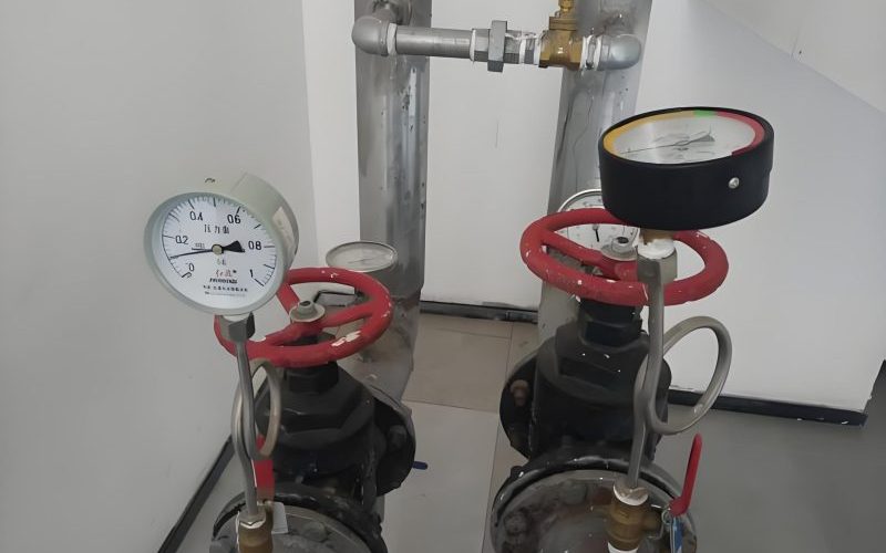
Pressure Loss Measurement in Hydraulic Lines
Pressure decreases as Hydraulic fluid flows through pipes and fittings due to friction losses.
Pressure Loss Factors in Hydraulic Systems
Flow Through Orifices and Clearances
The flow of Hydraulic fluid through small openings, orifices, and between closely fitting surfaces is fundamental to the operation of many hydraulic components, including valves, pumps, and actuators. Controlling this flow enables precise regulation of speed, force, and direction in hydraulic systems.hyd fluid.
Orifices are used in flow control valves, pressure relief valves, and as restrictors to regulate Hydraulic fluid flow. The flow rate through an orifice depends on several factors: the pressure difference across the orifice (Δp), the orifice area (A), the coefficient of discharge (C_d), and the density of the Hydraulic fluid (ρ). The general equation for flow through an orifice is Q = C_d * A * √(2Δp/ρ).
The coefficient of discharge accounts for energy losses and contraction of the flow stream (vena contracta) as it passes through the orifice. C_d typically ranges from 0.6 to 0.9 for sharp-edged orifices, depending on the Reynolds number and the ratio of orifice diameter to pipe diameter. For rounded orifices, C_d can approach 1.0 due to reduced energy losses.
Orifices can be categorized based on their relationship to the flow path:
- Sharp-edged orifices: Create significant pressure drops and have consistent discharge coefficients
- Rounded-edged orifices: Produce less pressure loss and higher flow rates for the same size
- Short-tube orifices: Cylindrical passages that may have different flow characteristics
- Variable orifices: Adjustable openings used in flow control valves to regulate Hydraulic fluid flow
Flow through clearances between mating surfaces is equally important, particularly in hydraulic pumps and motors where internal leakage affects efficiency. These clearances are typically very small (often microns) and form thin passages for Hydraulic fluid flow.
Flow between parallel plates is governed by the Navier-Stokes equations for laminar flow, resulting in the equation: Q = (w * h³ * Δp) / (12μL), where w is the width of the plates, h is the clearance, Δp is pressure difference, μ is dynamic viscosity, and L is the length of the clearance. This shows that flow rate is extremely sensitive to clearance height (cubed relationship) and directly proportional to the pressure difference across the clearance.
Flow through annular clearances (between cylinders and pistons) is similarly dependent on clearance size, pressure difference, and Hydraulic fluid viscosity. This type of flow is critical in hydraulic cylinders, where piston-to-cylinder clearances must be carefully controlled to minimize leakage while allowing smooth movement.
Understanding these flow characteristics allows engineers to design components with appropriate clearances, select suitable Hydraulic fluid viscosities, and predict leakage rates. This knowledge is essential for optimizing efficiency, controlling costs, and ensuring proper performance in hydraulic systems where precise flow control is necessary.
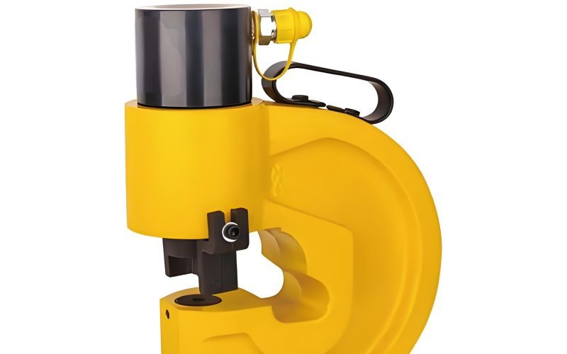
Hydraulic Fluid Flow Through Orifices
Orifice design significantly affects flow characteristics and pressure drops in Hydraulic fluid systems.
Flow vs. Clearance Relationship
Hydraulic Shock and Cavitation
Hydraulic shock and cavitation are two important phenomena that can significantly affect the performance, efficiency, and longevity of hydraulic systems. Both involve dynamic behavior of Hydraulic fluid and can cause damage if not properly managed.
Hydraulic shock (water hammer) occurs when there is a sudden change in the velocity of flowing Hydraulic fluid, resulting in large pressure transients. This typically happens when valves close quickly, stopping or redirecting flow, or when actuators suddenly decelerate. The rapid momentum change of the Hydraulic fluid creates pressure waves that travel through the system at the speed of sound in the fluid.Hydraulic transmission fluid.
The magnitude of pressure rise during hydraulic shock can be estimated using the Joukowsky equation: Δp = ρcΔv, where ρ is the density of the Hydraulic fluid, c is the speed of sound in the fluid, and Δv is the change in fluid velocity. Pressure spikes can reach several times the normal operating pressure, potentially exceeding component ratings and causing damage.
Effects of hydraulic shock include:
- Noise and vibration in the hydraulic system
- Damage to pipes, fittings, and components
- Seal failure and increased leakage of Hydraulic fluid
- Inaccurate operation of hydraulic components
- Premature fatigue failure of system components
Cavitation occurs when the pressure of Hydraulic fluid drops below its vapor pressure, causing the formation of vapor bubbles. These bubbles collapse violently when they move to regions of higher pressure, creating micro-jets and shock waves that can damage nearby surfaces.
Common causes of cavitation in hydraulic systems include:
- Restrictions in suction lines causing pressure drops
- Excessively high pump speeds creating low inlet pressures
- Low fluid levels in reservoirs exposing suction lines to air
- Clogged or improperly sized filters restricting flow
- Leaks in suction lines allowing air to enter the Hydraulic fluid
- High fluid temperatures increasing vapor pressure
Cavitation damage appears as pitting, erosion, or corrosion on metal surfaces, particularly in pump impellers, valve ports, and cylinder walls. In addition to physical damage, cavitation reduces system efficiency, increases noise and vibration, and can cause pump damage or failure.
Preventive measures for both phenomena include:
- Using properly sized components and avoiding sudden flow changes
- Installing accumulators to absorb pressure spikes from hydraulic shock
- Ensuring adequate suction line size and pressure for pumps
- Maintaining proper fluid levels and avoiding air entry into Hydraulic fluid
- Controlling Hydraulic fluid temperature within recommended ranges
- Using anti-cavitation valves in appropriate locations
- Regular maintenance to prevent restrictions and leaks
Proper system design, component selection, and maintenance practices are essential for minimizing the risks associated with hydraulic shock and cavitation, ensuring reliable operation and extending the service life of hydraulic systems and their components.
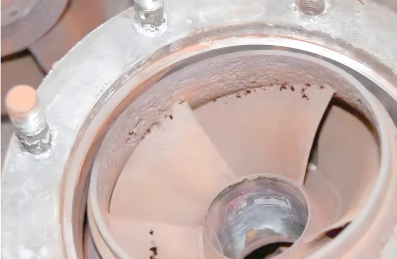
Cavitation Damage in Hydraulic Components
Vapor bubble collapse in Hydraulic fluid creates micro-jets that erode metal surfaces over time.
Pressure Transients During Hydraulic Shock
Conclusion
The principles of hydraulic fluid mechanics form the foundation for understanding and designing efficient hydraulic systems. From the physical properties that define Hydraulic fluid behavior to the complex dynamics of flow through various components, each aspect plays a crucial role in system performance.
By mastering these fundamentals—including fluid statics and dynamics, pressure loss calculations, flow characteristics through orifices and clearances, and the prevention of harmful phenomena like hydraulic shock and cavitation—engineers and technicians can optimize system design, select appropriate Hydraulic fluid, and ensure reliable, efficient operation of hydraulic equipment.Optical Transceiver.
Continued advancements in Hydraulic fluid technology and system design continue to improve efficiency, reduce environmental impact, and extend the capabilities of hydraulic systems across countless industrial applications.Electronic shelf labels.