
Fundamentals of Fluid Dynamics
Flow Laws and Core Equations for Hydraulic Engineering
Fluid dynamics is the study of fluid flow states, movement laws, energy conversion, and fluid-solid interactions. Its core lies in the continuity equation, Bernoulli's equation, and momentum equation, which serve as the theoretical foundation for analyzing and designing hydraulic technologies, particularly in the context of a hydraulic drive system. These principles are essential for understanding how liquids behave under various conditions and form the basis for efficient hydraulic drive system design and operation.
Whether analyzing simple pipe flows or complex hydraulic drive system configurations, a solid grasp of these fundamental concepts enables engineers to predict performance, optimize designs, and solve practical problems in fluid power applications. The principles of fluid dynamics find critical applications in virtually every hydraulic drive system, from industrial machinery to mobile equipment.
I. Basic Concept Analysis
1. Ideal Fluids and Flow States
For simplified analysis, "ideal fluids" are assumed to be inviscid and incompressible, with viscous effects corrected through experiments in practical applications. This idealization forms the basis for initial hydraulic drive system analysis, allowing engineers to develop fundamental designs before incorporating real-world complexities.
Fluid flow is categorized into steady flow (where parameters such as pressure and velocity at any point do not change with time) and unsteady flow (where parameters change over time). In a typical hydraulic drive system, steady flow conditions are often desirable for consistent performance, though transient or unsteady conditions must be considered during startup, shutdown, or rapid changes in operation.
Flow can also be classified by dimensionality: one-dimensional (linear flow, often simplified in engineering applications), two-dimensional, and three-dimensional flow. Most hydraulic drive system analyses utilize one-dimensional flow assumptions to simplify calculations while still providing accurate enough results for practical design purposes. This dimensional simplification is crucial in optimizing hydraulic drive system performance.
2. Streamlines and Flow Rate
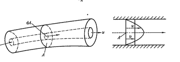
Streamlines are curves that instantaneously indicate the direction of fluid flow; they do not intersect and are smooth. A flow tube is formed by a closed curve of streamlines, with the collection of internal streamlines forming a flow bundle. The cross-section perpendicular to the flow bundle is the flow cross-section. Understanding streamline patterns is essential for optimizing fluid passage design in a hydraulic drive system.
Flow rate refers to the volume of liquid passing through a flow cross-section per unit time. Due to non-uniform velocity distribution caused by viscosity in actual fluid flow, the concept of average velocity is introduced – the equivalent velocity assuming uniform velocity distribution. The calculation formula is:
v = q/A
where q is the flow rate and A is the flow area
This average velocity directly corresponds to the piston speed in hydraulic cylinders, a critical parameter in any hydraulic drive system. Controlling and predicting this velocity is fundamental to hydraulic drive system performance, as it determines the speed of actuators and overall system productivity.
3. Flow Regimes and Reynolds Number
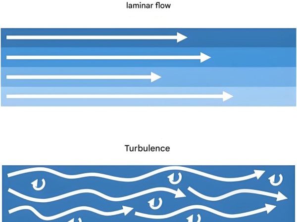
There are two primary flow regimes in fluid dynamics: laminar flow (stratified flow with minimal interference between layers) and turbulent flow (completely chaotic flow). The transition between these regimes is determined by the Reynolds number (Re), a dimensionless quantity that plays a crucial role in hydraulic drive system design and analysis.
The Reynolds number is calculated using the formula:
Re = vd/ν
where v is average velocity, d is pipe inner diameter, and ν is kinematic viscosity
The Reynolds number represents the ratio of inertial forces to viscous forces. Flow is laminar when the Reynolds number is below a critical value (2320 for smooth metal circular pipes) and turbulent when it exceeds this value. This distinction is vital in hydraulic drive system design because pressure losses, heat generation, and component wear vary significantly between laminar and turbulent flow conditions.
For non-circular cross-sections, the hydraulic diameter is used to calculate the Reynolds number:
dh = 4A/χ
where A is the cross-sectional area and χ is the wetted perimeter
Properly accounting for the Reynolds number allows engineers to optimize hydraulic drive system components, ensuring efficient operation with minimal energy loss. In a well-designed hydraulic drive system, flow conditions are carefully controlled to maintain desirable Reynolds numbers for specific components and operating conditions.
II. Three Core Equations
1. Continuity Equation (Conservation of Mass)
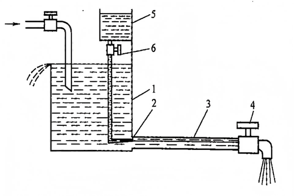
The continuity equation is a fundamental principle in fluid dynamics that expresses the conservation of mass. In steady flow, assuming incompressibility, the mass flow rate through any flow cross-section remains constant. This principle is essential for understanding and designing hydraulic drive system components, as it governs how fluid moves through different parts of the system.
Mathematically, the continuity equation is expressed as:
v1A1 = v2A2 = q
where v is velocity, A is cross-sectional area, and q is flow rate
The key conclusion from this equation is that in a closed pipeline, the flow rate remains constant, and the velocity is inversely proportional to the flow area. This principle directly impacts hydraulic drive system design, particularly in components like hydraulic cylinders, where varying cross-sectional areas create the force and motion characteristics essential to the system's function.
In a hydraulic drive system, the continuity equation explains how fluid flows through different components, from pumps to valves to actuators. For example, when fluid moves from a larger diameter pipe to a smaller one in a hydraulic drive system, the velocity increases proportionally to maintain constant flow rate, a phenomenon engineers leverage to control actuator speeds and forces.
2. Bernoulli's Equation (Conservation of Energy)
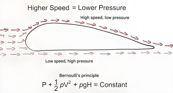
Bernoulli's equation describes the conservation of energy in a flowing fluid, stating that the total mechanical energy per unit mass remains constant along a streamline, assuming no energy losses. This principle is fundamental to analyzing pressure and velocity relationships in a hydraulic drive system, helping engineers predict performance and identify energy losses.
For ideal fluids (no viscosity, no energy losses), the equation is:
p1/ρ + u12/2 + gh1 = p2/ρ + u22/2 + gh2
where p is pressure, ρ is density, u is velocity, g is gravity, and h is elevation
This equation shows that the sum of pressure energy, kinetic energy, and potential energy per unit mass remains constant in an ideal fluid. In a hydraulic drive system, this means energy can transform between these forms – for example, pressure energy from a pump can convert to kinetic energy in a valve or potential energy in a raised cylinder.
For real fluids, viscosity causes energy losses, requiring modifications to Bernoulli's equation:
p1/ρ + α1v12/2 + gh1 = p2/ρ + α2v22/2 + gh2 + ghw
where α is the kinetic energy correction factor and hwg accounts for energy losses
The kinetic energy correction factor (α = 2 for laminar flow, α = 1 for turbulent flow) accounts for non-uniform velocity profiles. The term ghw represents energy losses due to friction, a critical consideration in hydraulic drive system design. Minimizing these losses improves hydraulic drive system efficiency, reducing energy consumption and heat generation.
Bernoulli's equation is particularly useful in analyzing components like nozzles, diffusers, and valves within a hydraulic drive system. It helps engineers understand how pressure changes as fluid moves through different parts of the hydraulic drive system, enabling optimization of component design for maximum efficiency and performance.
3. Momentum Equation (Momentum Theorem)
The momentum equation in fluid dynamics is derived from Newton's second law of motion and is used to calculate the forces exerted by fluid flow on solid surfaces. This is particularly important in hydraulic drive system design, as it helps predict the forces acting on components like valves, bends, and actuators, which is essential for ensuring structural integrity and proper operation.
The momentum equation is expressed as:
F = ρq(β2v2 - β1v1)
where β is the momentum correction factor (β = 1 for turbulent flow, β = 4/3 for laminar flow)
The reaction force to this is known as the steady-state fluid force, which is a critical consideration in many hydraulic drive system components. For example, in spool valves commonly found in a hydraulic drive system, the fluid force often tends to close the valve, a phenomenon engineers must account for when designing valve actuation systems.
Understanding these fluid forces is essential for designing reliable hydraulic drive system components. Excessive forces can lead to premature wear, reduced efficiency, or even component failure. By applying the momentum equation, engineers can predict these forces and design appropriate countermeasures, such as balancing features or larger actuators, to ensure proper hydraulic drive system operation.
In a typical hydraulic drive system, the momentum equation is used to analyze and design components like directional control valves, hydraulic motors, and cylinder end caps. It helps engineers determine the appropriate size and strength of these components to withstand the forces generated during operation, ensuring safe and efficient performance of the entire hydraulic drive system.
The momentum equation also plays a crucial role in understanding and predicting the behavior of hydraulic drive system under dynamic conditions. By analyzing how momentum changes with time, engineers can design systems that respond appropriately to varying loads and operating conditions, enhancing the overall performance and responsiveness of the hydraulic drive system.
Conclusion
These fundamental theories not only reveal the intrinsic laws of fluid flow but also provide a key basis for the design and optimization of hydraulic systems. From the basic concepts of flow regimes and Reynolds numbers to the core equations governing mass, energy, and momentum conservation, these principles form the foundation of modern hydraulic engineering.
A thorough understanding of these fluid dynamics fundamentals is essential for anyone involved in the design, analysis, or maintenance of a hydraulic drive system. By applying these principles, engineers can develop more efficient, reliable, and cost-effective hydraulic drive system solutions for a wide range of industrial and mobile applications.
Learn more