The Complete Technical Guide to Hydraulic Cylinders
A comprehensive resource covering principles, calculations, structures, and design considerations for Hydraulic Cylinders
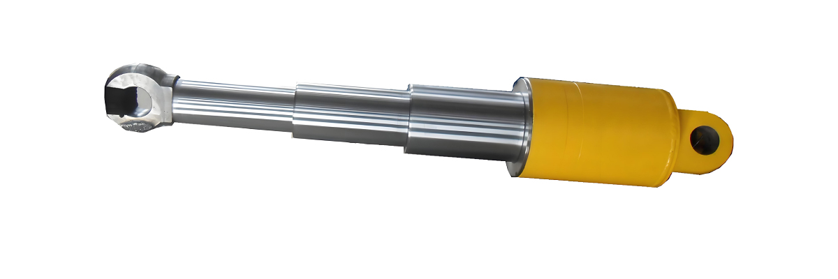
Table of Contents
1. Working Principles, Types, and Characteristics of Hydraulic Cylinders
Hydraulic Cylinders are mechanical actuators that convert hydraulic energy into linear mechanical force and motion, a principle used in hydrostatic drive transmission. They operate based on Pascal's law, which states that pressure applied to an enclosed fluid is transmitted undiminished to all portions of the fluid and the walls of its container.
Working Principles
The basic working principle of Hydraulic Cylinders involves the use of a pressurized hydraulic fluid, typically oil, to extend and retract a piston rod. When hydraulic fluid is pumped into one end of the cylinder, it pushes against the piston, creating linear motion. The opposite end of the cylinder either vents fluid back to the reservoir or receives fluid under pressure for the return stroke.
This process allows Hydraulic Cylinders to generate significant force relative to their size, making them ideal for heavy-duty industrial applications. The force generated is directly proportional to the pressure of the hydraulic fluid and the cross-sectional area of the piston.
Types of Hydraulic Cylinders
There are several distinct types of Hydraulic Cylinders, each designed for specific applications:
1. Single-Acting Cylinders
Single-acting Hydraulic Cylinders use hydraulic pressure to extend the piston rod, while a spring or external force (such as gravity) is used to retract it. These cylinders are simpler in design and more cost-effective for applications where only one direction of force is required.
2. Double-Acting Cylinders
Double-acting Hydraulic Cylinders use hydraulic pressure for both extension and retraction strokes. Fluid is alternately applied to both sides of the piston, allowing for controlled movement in both directions. This type is more versatile and commonly used in industrial applications.
3. Telescopic Cylinders
Telescopic Hydraulic Cylinders feature a series of nested tubes (called stages) that allow for extended stroke lengths while maintaining a compact retracted length. These are commonly used in applications requiring long reach, such as dump trucks and cranes.
4. Rodless Cylinders
Rodless Hydraulic Cylinders do not have an external piston rod. Instead, they use an internal piston connected to an external carriage. These cylinders are ideal for applications where space is limited and a long stroke is required without extending beyond the cylinder body.
Key Characteristics
Hydraulic Cylinders offer several important characteristics that make them valuable in industrial applications:
- High force output relative to size and weight
- Precise control of speed and position
- Ability to maintain force and pressure without continuous energy input
- Compact design for space-constrained applications
- Durability and long service life in harsh environments
- Wide range of operating pressures (typically 1,000 to 5,000 psi)
- Capability to operate in extreme temperatures
Hydraulic Cylinder Working Principle
Basic operation of a double-acting hydraulic cylinder
Types of Hydraulic Cylinders
Comparison of single-acting, double-acting, and telescopic designs
Performance Characteristics
Force output comparison across different cylinder sizes
2. Calculation of Basic Parameters for Hydraulic Cylinders
Properly calculating the basic parameters of Hydraulic Cylinders is essential for ensuring optimal performance and longevity in any application, alongside factors like transmission hydraulic fluid. These calculations determine the cylinder's ability to generate force, its speed, and the required hydraulic system pressure.
Force Calculation
The primary function of Hydraulic Cylinders is to generate force. The force output (F) of a hydraulic cylinder is calculated using the formula:
Where:
- F = Force (in Newtons or pounds-force)
- P = Pressure (in Pascals or pounds per square inch)
- A = Effective area of the piston (in square meters or square inches)
For double-acting Hydraulic Cylinders, two force calculations are necessary: one for the extend stroke (using the full piston area) and one for the retract stroke (using the piston area minus the rod area).
Extend Stroke Force
Where D is the piston diameter.
Retract Stroke Force
Where d is the rod diameter.
Speed Calculation
The speed (v) of Hydraulic Cylinders is determined by the flow rate (Q) of hydraulic fluid and the effective area (A) of the piston:
For extend stroke speed:
For retract stroke speed:
Pressure Requirements
When selecting Hydraulic Cylinders, it's crucial to determine the required system pressure based on the load and cylinder size:
Cylinder Displacement
The displacement (V) of Hydraulic Cylinders is the volume of fluid required to extend the cylinder over its stroke length (L):
Power Calculation
The hydraulic power (P) required to operate Hydraulic Cylinders is calculated as:
Where P_system is the operating pressure and Q is the flow rate.
Example Calculation
For a double-acting hydraulic cylinder with:
- Piston diameter (D) = 100 mm
- Rod diameter (d) = 50 mm
- System pressure (P) = 15 MPa
- Flow rate (Q) = 50 L/min
Extend force calculation:
F_extend = 15,000,000 Pa × 0.00785 m² = 117,750 N ≈ 12,000 kgf
Retract force calculation:
F_retract = 15,000,000 Pa × 0.00589 m² = 88,350 N ≈ 9,000 kgf
Hydraulic Cylinder Dimensions
Key dimensions used in cylinder calculations
Pressure-Force Relationship
Force output at various pressures for different cylinder sizes
Cylinder Sizing Calculator
Required piston diameter: ~89 mm
3. Typical Structures of Hydraulic Cylinders
The structure of Hydraulic Cylinders in hydraulic transmission jack varies depending on their application, but most share common components designed to convert hydraulic energy into linear motion efficiently and reliably.
Basic Components
All Hydraulic Cylinders consist of several key components working together to produce linear motion:
1. Cylinder Barrel (Tube)
The cylinder barrel is a cylindrical tube that contains the hydraulic fluid and guides the piston. It is typically made from high-strength steel, honed to a smooth finish to minimize friction and wear. The barrel features ports for fluid inlet and outlet, allowing hydraulic fluid to enter and exit during operation.
2. Piston
The piston is a cylindrical component that fits closely inside the cylinder barrel. It separates the two chambers of the cylinder and transmits force from the hydraulic fluid to the piston rod. Pistons are usually fitted with seals to prevent fluid leakage between chambers.
3. Piston Rod
The piston rod connects the piston to the external load. It is typically a high-strength steel rod that extends through one end of the cylinder. The rod must be precisely machined and often hardened or coated (with chrome, for example) to resist wear and corrosion.
4. Rod Gland (Head)
The rod gland, or head, is the component through which the piston rod exits the cylinder barrel. It contains seals to prevent fluid leakage around the rod and often includes bearings or bushings to guide the rod and reduce friction.
5. Cylinder Base (Cap)
The cylinder base, or cap, closes the opposite end of the cylinder barrel from the rod gland. It may be welded, threaded, or bolted to the barrel and provides a mounting point for the cylinder.
6. Seals and Wipers
Seals are critical components in Hydraulic Cylinders, preventing fluid leakage and contamination. Common seal types include O-rings, U-cups, v-rings, and piston cups. Wipers are specialized seals that remove contaminants from the piston rod as it retracts, preventing damage to internal components.
Mounting Configurations
Hydraulic Cylinders are available with various mounting configurations to suit different applications:
Flange Mounts
Flat flanges on cylinder ends for bolted attachment
Trunnion Mounts
Pins through the cylinder barrel for pivot mounting
Clevis Mounts
U-shaped brackets for pivot connection to structures
Foot Mounts
Flat surfaces for mounting to bases or plates
Lug Mounts
Protruding lugs with holes for bolted attachment
Threaded Mounts
Threads on cylinder ends for direct mounting
Specialized Structures
Certain applications require Hydraulic Cylinders with specialized structures:
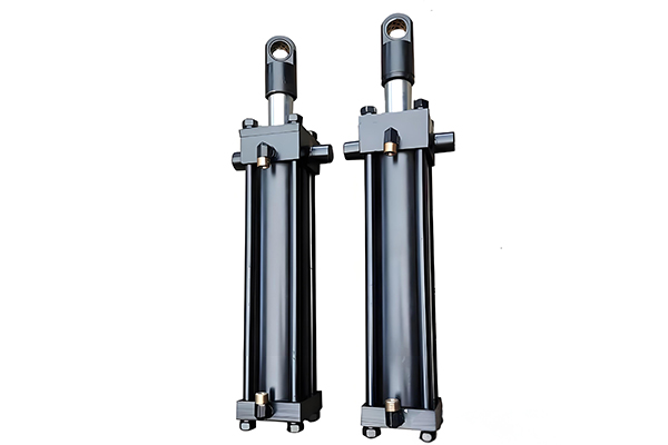
1. Tie-Rod Cylinders
These cylinders use high-strength tie rods to hold the end caps to the barrel. They are easy to disassemble for maintenance and are common in industrial applications.
2. Welded Cylinders
Welded cylinders have end caps welded directly to the barrel, creating a more compact design with higher structural integrity. They are commonly used in mobile equipment.
3. Telescopic Cylinders
As mentioned earlier, telescopic Hydraulic Cylinders feature multiple nested stages that allow for long strokes while maintaining a compact retracted length. Each stage acts as a barrel for the next smaller stage.
4. Hollow Piston Rod Cylinders
These cylinders have a hollow piston rod, allowing for applications where another component (such as a tie rod or sensor cable) needs to pass through the center of the cylinder.
Hydraulic Cylinder Cross-Section
Key components:
- Cylinder barrel
- Piston
- Piston rod
- Rod gland with seals
- Cylinder base
- Hydraulic ports
- Mounting lugs
Seal Configurations
Various seal designs for different pressure and temperature ranges
Mounting Types Comparison
Performance characteristics of different mounting configurations
4. Design and Calculation of Hydraulic Cylinders
The design process for Hydraulic Cylinders involves careful hydromechanical consideration of multiple factors to ensure the final product meets performance requirements while maintaining reliability and longevity in its intended application.
Design Considerations
Several critical factors influence the design of Hydraulic Cylinders:
1. Application Requirements
The specific application dictates many design parameters, including required force, stroke length, operating speed, duty cycle, and environmental conditions. Mobile applications often have different requirements than industrial fixed-mount applications.
2. Load Analysis
Thorough load analysis is essential, considering not just static loads but also dynamic forces, shock loads, and side loads. Side loads can significantly affect cylinder life and often require special design considerations such as larger rod diameters or guide bushings.
3. Operating Pressure
The system operating pressure influences material selection, wall thickness, and overall cylinder dimensions. Hydraulic Cylinders are typically designed for specific pressure ranges, with common industrial cylinders rated for 100-300 bar (1,500-4,350 psi) and high-pressure cylinders rated up to 700 bar (10,000 psi) or more.
4. Temperature Range
Operating temperature affects seal material selection and hydraulic fluid properties. Cylinders designed for extreme temperatures require specialized seals and possibly insulation or heat dissipation features.
5. Environmental Factors
Environmental conditions such as humidity, exposure to chemicals, dust, or corrosive substances must be considered. Special coatings, materials, or protective features may be required for Hydraulic Cylinders operating in harsh environments.
Material Selection
Proper material selection is critical for the performance and durability of Hydraulic Cylinders:
1. Cylinder Barrel
Most cylinder barrels are made from high-quality carbon steel (such as SAE 1020-1045) or alloy steel. For corrosive environments, stainless steel or steel with special coatings may be used. The barrel must be precisely honed to achieve a smooth surface finish (typically 0.2-0.4 μm Ra).
2. Piston Rod
Piston rods are usually made from high-strength carbon steel (SAE 4140 or 4340) that is heat-treated for strength. They are typically chrome-plated (0.0005-0.0015 inches thick) to provide corrosion resistance and a hard, wear-resistant surface.
3. End Caps and Flanges
These components are often made from ductile iron or carbon steel. For lightweight applications, aluminum alloys may be used where strength requirements allow.
4. Seals
Seal materials include nitrile rubber (standard applications), polyurethane (abrasion resistance), Viton (high temperature), and PTFE (chemical resistance). The choice depends on operating temperature, pressure, and fluid compatibility.
Structural Calculations
Several structural calculations are necessary during the design of Hydraulic Cylinders:
1. Barrel Wall Thickness
The required wall thickness (t) of the cylinder barrel is calculated based on the maximum operating pressure and material strength:
Where:
- P = Maximum operating pressure
- D = Inside diameter of the barrel
- S = Allowable stress of the barrel material
- F.S. = Factor of safety (typically 2-4)
2. Piston Rod Diameter
The piston rod must be sized to resist both compressive and tensile loads. For compressive loads, the rod diameter is determined based on buckling considerations using the Euler formula:
Where:
- E = Modulus of elasticity of the rod material
- I = Moment of inertia of the rod cross-section
- L = Effective length of the rod
3. Bearing Calculations
The rod gland bearings must be sized to handle radial loads without excessive wear. The specific pressure on the bearing surface should be within recommended limits for the bearing material:
Where F_radial is the radial load, d is the rod diameter, and L_bearing is the bearing length.
Design Verification
Finite Element Analysis (FEA) is often used to verify the design of Hydraulic Cylinders, particularly for critical applications. FEA can simulate stress distribution, deflection, and fatigue life under various operating conditions.
Prototyping and testing are also essential steps in the design process, ensuring that the cylinder meets all performance requirements before full-scale production.Optical Transceiver.
Hydraulic Cylinder Design Process
Step-by-step design methodology for optimal performance
Material Selection Guide
| Component | Common Materials |
|---|---|
| Cylinder Barrel | SAE 1020-1045 steel |
| Piston Rod | SAE 4140/4340, chrome plated |
| End Caps | Ductile iron, carbon steel |
| Piston | Cast iron, steel, aluminum |
| Seals | Nitrile, polyurethane, Viton |
| Bearings | Bronze, composite materials |
Stress Analysis Visualization
Simulated stress distribution in a hydraulic cylinder under load
Summary of Hydraulic Cylinder Technology
Hydraulic Cylinders are versatile and powerful actuators that play a critical role in countless industrial and mobile applications. Proper understanding of their working principles, parameter calculations, structural components, and design considerations is essential for selecting, applying, and maintaining these components effectively. By following the engineering principles outlined in this guide, you can ensure optimal performance, reliability, and longevity from your hydraulic cylinder systems.Electronic shelf labels.