Hydraulic systems rely on more than just pumps and cylinders to function effectively. The auxiliary components play a crucial role in maintaining system integrity, performance, and longevity. This guide explores the key Hydraulic components that form the backbone of any well-designed hydraulic system, from filtration to sealing solutions.
Understanding these components is essential for engineers, maintenance professionals, and anyone involved in specifying or operating hydraulic equipment. Each component serves a unique purpose, yet they work together seamlessly to ensure optimal system performance.
Filters
In any hydraulic system, maintaining fluid cleanliness is paramount to prevent component wear, reduce downtime, and extend service life. Filters are critical Hydraulic components designed to remove contaminants from hydraulic fluids like universal hydraulic oil, ensuring system reliability even in harsh operating conditions.
Hydraulic fluid contamination can originate from various sources including manufacturing residues, wear particles, environmental dust, and moisture. These contaminants can cause abrasive wear, surface fatigue, and clogging of critical components like valves and orifices.
There are several types of hydraulic filters designed for specific applications:
- Suction Filters: Installed on the pump inlet to protect the pump from large contaminants. These typically have lower pressure ratings and higher dirt-holding capacity.
- Return Line Filters: Positioned in the return line to the reservoir, these filters remove contaminants generated during system operation before they enter the reservoir.
- Pressure Line Filters: Located downstream of the pump to protect sensitive components from contamination. These filters must withstand high system pressures.
- Off-line Filters (Kidney Loops): Operate continuously to clean oil independently of the main system, providing continuous filtration and conditioning.
Filter performance is rated by several key parameters including micron rating (the size of particles removed), pressure drop, dirt-holding capacity, and flow rate. The appropriate filter selection depends on the system's sensitivity to contamination, operating pressure, and fluid viscosity.
Modern filters often incorporate visual or electrical differential pressure indicators that signal when maintenance is required. This proactive approach to filter maintenance ensures that Hydraulic components remain protected throughout their operating cycle.
Proper filter maintenance is as important as selection. Regular replacement or cleaning according to manufacturer specifications prevents filter bypass (where contaminated fluid flows around a clogged filter) and maintains system cleanliness.
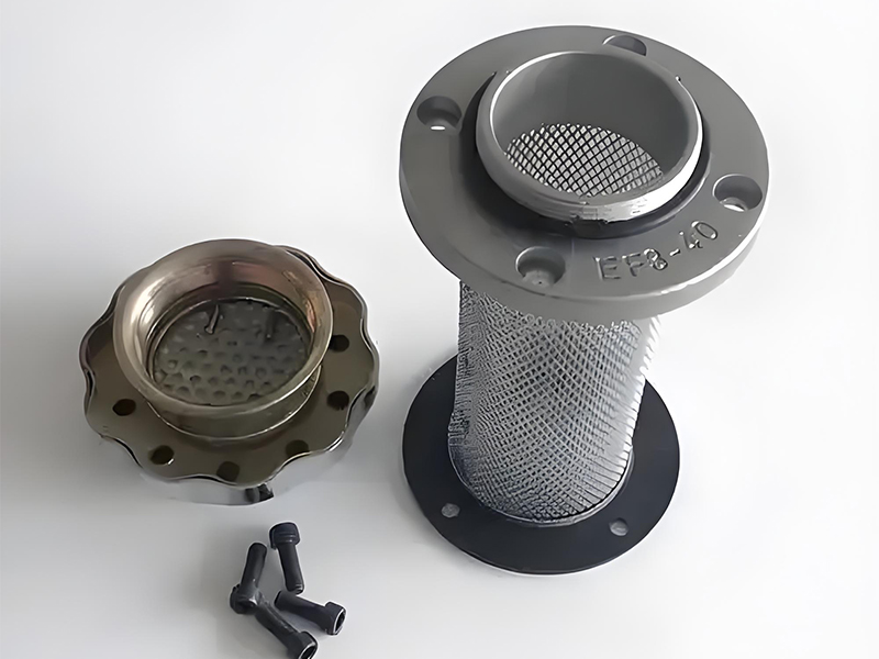
Hydraulic Filter Assemblies
Various filter types used in hydraulic systems to maintain fluid cleanliness and protect critical Hydraulic components.
Filter Performance Comparison
Accumulators
Accumulators are versatile Hydraulic components that store potential energy in the form of compressed gas or a spring, which can be released as hydraulic fluid like universal tractor hydraulic oil under pressure when needed. This energy storage capability provides numerous benefits in hydraulic systems.
The basic principle of an accumulator involves a gas chamber separated from a fluid chamber by a piston, bladder, or diaphragm. When fluid is pumped into the accumulator, it compresses the gas, storing energy. When system pressure drops, the compressed gas expands, forcing fluid back into the system.
There are several types of accumulators, each with specific advantages:
- Bladder Accumulators: Feature a flexible bladder that separates gas and fluid, offering rapid response and good gas retention.
- Piston Accumulators: Use a piston to separate gas and fluid, suitable for high-pressure applications and large volume capacities.
- Diaphragm Accumulators: Utilize a flexible diaphragm, providing excellent response times for small volume applications.
- Spring-Loaded Accumulators: Use mechanical springs instead of gas, offering simplicity but limited pressure and volume capabilities.
Accumulators serve multiple functions in hydraulic systems including energy storage for peak demand periods, which allows the use of smaller pumps. They absorb pressure pulsations and hydraulic shocks, protecting sensitive Hydraulic components from damage.
In emergency situations, accumulators can provide a limited supply of pressurized fluid for safe system shutdown. They also help maintain constant pressure in systems with varying flow demands and compensate for fluid volume changes due to temperature variations.
Proper sizing and selection of accumulators depend on application requirements such as volume capacity, pressure range, response time, and operating environment. Regular maintenance includes checking precharge pressure, inspecting for leaks, and verifying proper operation of associated valves.
Accumulator Designs
Various accumulator types demonstrate the diversity of these essential Hydraulic components.
Energy Storage
Captures and releases energy efficiently
Shock Absorption
Protects system components
Pressure Stabilization
Reduces system pulsations
Emergency Power
Provides backup operation
Reservoirs
The reservoir serves as the central hub for fluid in a hydraulic system, performing multiple critical functions that support the operation of all other Hydraulic components. Beyond simply storing hydraulic fluid like tractor hydraulic oil, reservoirs help maintain system performance and protect components.
One of the primary functions of a reservoir is to allow contaminants to settle out of the fluid. By providing a low-velocity zone, heavier particles can fall to the bottom where they can be removed during maintenance. Many reservoirs incorporate baffles to create flow paths that enhance this settling process.
Heat dissipation is another crucial role of the reservoir. Hydraulic systems generate heat during operation, and the reservoir's large surface area helps dissipate this heat to the surrounding environment. Some applications utilize finned reservoirs or additional cooling coils to enhance this heat transfer.
Reservoirs also help separate air from the hydraulic fluid. Properly designed reservoirs include features that allow entrained air to escape, preventing cavitation in pumps and ensuring efficient operation of all Hydraulic components.
Reservoir design considerations include:
- Capacity: Typically 3-5 times the pump flow rate per minute, allowing adequate residence time for cooling and air separation.
- Material: Steel is common for industrial applications, while aluminum may be used for lighter weight requirements.
- Construction: Welded or bolted designs with internal baffles, proper inlet/outlet positioning, and drain plugs.
- Accessories: Level indicators, filler breathers, drain valves, and clean-out covers for maintenance.
Proper reservoir maintenance includes regular fluid level checks, periodic sampling for contamination analysis, and scheduled fluid replacement. The reservoir should be cleaned thoroughly during major system overhauls to remove accumulated sludge and contaminants.
In mobile hydraulic applications, reservoirs are often integrated into machine structures to save space and weight, while industrial systems typically use standalone reservoirs designed for specific flow rates and cooling requirements.
Hydraulic Reservoir Design
Anatomical view of a reservoir showing key features that support other Hydraulic components.
Reservoir Sizing Guidelines
| System Type | Recommended Capacity |
|---|---|
| Industrial Fixed Systems | 3-5 × pump flow rate (gpm) |
| Mobile Equipment | 1-2 × pump flow rate (gpm) |
| High Heat Load Systems | 5-10 × pump flow rate (gpm) |
| Systems with Accumulators | 4-7 × pump flow rate (gpm) |
Heat Exchangers
Hydraulic systems inherently generate heat due to fluid friction with hydraulic oil for tractors, pressure drops, and inefficiencies in Hydraulic components. Heat exchangers are specialized devices designed to manage this thermal energy, maintaining optimal operating temperatures and preventing system degradation.
Excessive heat is one of the most common causes of hydraulic system failure. Elevated temperatures accelerate fluid degradation, reduce viscosity, increase oxidation rates, and cause premature wear of seals and other components. Maintaining fluid temperatures within the recommended range (typically 120-140°F or 49-60°C) is essential for system longevity.
There are several types of heat exchangers used in hydraulic systems:
- Air-Cooled Heat Exchangers: Use ambient air to dissipate heat, often with fans to enhance airflow. These are simple, cost-effective, and suitable for mobile and small industrial applications.
- Water-Cooled Heat Exchangers: Utilize cooling water (or other liquids) to remove heat, offering higher efficiency than air-cooled models. These require a separate water supply but are ideal for high-heat-load applications.
- Plate Heat Exchangers: Consist of stacked plates with alternating passages for hydraulic fluid and cooling medium, providing large surface area in a compact design.
- Shell and Tube Heat Exchangers: Feature a shell containing a bundle of tubes, with one fluid flowing through the tubes and the other around them. These are robust and suitable for high-pressure applications.
Heat exchanger selection depends on several factors including heat load (calculated in British Thermal Units or BTUs), available cooling medium, space constraints, and environmental conditions. Proper sizing is critical - an undersized unit will fail to maintain adequate temperatures, while an oversized unit increases cost and energy consumption.
Integration of heat exchangers into hydraulic systems often includes thermostatic controls that activate cooling only when needed, optimizing energy usage. Some systems utilize heat recovery, capturing waste heat for useful purposes like space heating.
Maintenance requirements vary by type but generally include periodic cleaning of heat transfer surfaces to remove fouling, which reduces efficiency. Air-cooled units require filter maintenance to prevent debris accumulation on fins, while water-cooled systems may need water treatment to prevent scaling and corrosion.
By effectively managing thermal conditions, heat exchangers protect Hydraulic components from heat-related damage, extend fluid life, and maintain consistent system performance across varying operating conditions.
Hydraulic Heat Exchangers
Air-cooled and water-cooled designs for temperature control of Hydraulic components.
Effects of Temperature on Hydraulic Fluid
Connectors
Connectors are the unsung heroes of hydraulic systems, providing the critical links between various Hydraulic components while ensuring reliable transfer of fluids like tractor transmission fluid under pressure. These components must provide secure, leak-free connections that can withstand system pressures, vibration, and environmental conditions.
The performance of a hydraulic system is only as good as its connections. Even small leaks can lead to significant fluid loss, reduced system efficiency, environmental contamination, and potential safety hazards. Proper connector selection and installation are therefore essential for system reliability.
Hydraulic connectors come in various types and configurations to suit different applications:
- Tube Fittings: Used with rigid tubing, available in flared, flareless, and compression styles. These provide permanent, high-pressure connections.
- Hose Fittings: Designed for use with flexible hydraulic hoses, featuring crimped or reusable designs that accommodate movement and vibration.
- Quick Disconnect Couplings: Allow for rapid connection and disconnection of hydraulic lines without fluid loss, facilitating maintenance and component replacement.
- Flanges: Used for high-flow, high-pressure applications, providing a robust connection method for large-diameter lines.
- Adapters: Enable connections between different thread types, sizes, or styles, providing flexibility in system design.
Connector specifications include pressure rating, thread type (metric, BSP, NPT, etc.), material (steel, stainless steel, brass), and sealing method (O-ring, metal-to-metal, cone-and-thread). The material selection must consider compatibility with the hydraulic fluid and environmental factors like corrosion potential.
Proper installation techniques are critical for connector performance. This includes correct torque values for threaded connections, proper flaring of tube ends, and appropriate crimping parameters for hose assemblies. Many connectors incorporate anti-vibration features to maintain integrity in dynamic applications.
In recent years, push-to-connect fittings have gained popularity for certain applications, allowing tool-free assembly while maintaining reliable performance. These innovations reduce installation time while ensuring proper connection.
Regular inspection of connectors is part of effective hydraulic system maintenance. Signs of leakage, corrosion, or damage should be addressed promptly to prevent system failure. When replacing connectors, using components that meet or exceed original specifications ensures compatibility with other Hydraulic components and system requirements.
Hydraulic Connector Types
Diverse connector solutions for joining Hydraulic components in various applications.
Connector Selection Criteria
- System pressure rating
- Flow rate requirements
- Fluid compatibility
- Temperature range
- Vibration and movement
- Environmental conditions
Installation Best Practices
- Use proper torque specifications
- Avoid over-tightening
- Ensure proper alignment
- Use appropriate thread sealant
- Inspect for damage before installation
- Follow proper crimp procedures
Sealing Devices
Sealing devices are critical Hydraulic components that prevent leakage of transmission fluid vs hydraulic oil between mating surfaces, contain pressure, and exclude contaminants from entering hydraulic systems. The effectiveness of these seals directly impacts system efficiency, reliability, and safety.
Hydraulic seals must perform under challenging conditions including high pressures, wide temperature ranges, exposure to hydraulic fluids, and dynamic motion between components. The failure of a single seal can lead to costly downtime, environmental contamination, and damage to other system components.
There are numerous types of sealing devices designed for specific applications:
- O-Rings: Simple, cost-effective circular seals used in both static and dynamic applications. Available in various materials and sizes to suit different pressures and fluids.
- Piston Seals: Designed to prevent fluid leakage between the piston and cylinder bore in hydraulic cylinders, available in single-acting and double-acting configurations.
- Rod Seals: Installed in cylinder heads to prevent fluid leakage around the piston rod while excluding contaminants from entering the cylinder.
- Wiper Seals: Secondary seals that remove contaminants from rod surfaces as they retract into cylinders, protecting internal components.
- U-Cups: Symmetrical or asymmetrical seals used in hydraulic cylinders and valves, providing excellent sealing under pressure.
- V-Rings: Multiple-lip seals used for rod and piston applications requiring enhanced sealing performance under varying conditions.
- Gaskets: Flat seals used between stationary surfaces, available in various materials and configurations.
Seal material selection is critical and depends on factors including operating temperature range, fluid compatibility, pressure rating, and dynamic vs. static application. Common materials include nitrile rubber (NBR), fluorocarbon (Viton®), polyurethane, ethylene propylene (EPDM), and PTFE-based compounds.
Proper seal installation is essential for optimal performance. This includes ensuring clean mating surfaces, using proper installation tools to prevent damage, maintaining correct clearance dimensions, and applying appropriate lubrication compatible with both the seal material and hydraulic fluid.
Seal failure analysis can provide valuable insights into system issues. Common failure modes include extrusion (due to excessive clearance), abrasion (from contaminants), chemical attack (from incompatible fluids), and compression set (permanent deformation from prolonged pressure or temperature exposure).
Regular inspection of seals as part of preventive maintenance helps identify wear before failure occurs. When replacing seals, using high-quality components designed for the specific application ensures compatibility with other Hydraulic components and extends service life.
Hydraulic Sealing Devices
Essential sealing solutions that maintain integrity between Hydraulic components.
Seal Material Comparison
Integrated Hydraulic System Performance
Each category of auxiliary Hydraulic components plays a vital role in system performance, and their proper selection, installation, and maintenance are essential for reliable operation. While each component serves a specific function, they work together as a system, and the performance of any one component affects the entire system.
A well-designed hydraulic system incorporates high-quality filters to maintain fluid cleanliness, accumulators to manage energy and pressure fluctuations, properly sized reservoirs for fluid management, efficient heat exchangers to control temperature, reliable connectors for leak-free operation, and effective sealing devices to contain pressure and prevent contamination.Optical Transceiver.
By understanding the functions, selection criteria, and maintenance requirements of these auxiliary Hydraulic components, engineers and maintenance professionals can optimize system performance, minimize downtime, and extend the service life of hydraulic equipment.Electronic shelf labels.