Hydraulic Transmission Technology
Understanding the fundamental principles and components that power modern hydraulic systems
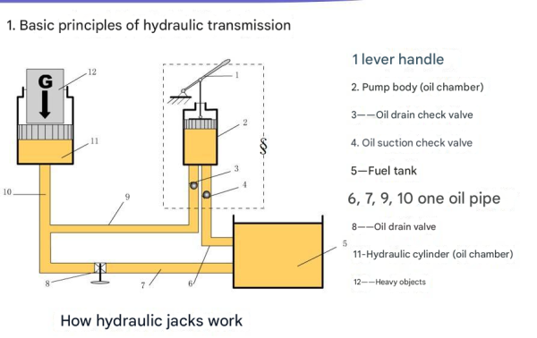
Hydraulic transmission is a critical technology in countless industrial applications, from manufacturing machinery to construction equipment. At its core, the question of how does a hydrostatic transmission work revolves around the transfer of power through pressurized fluid. This page explores the working principles and essential components of hydraulic systems, providing a comprehensive understanding of this vital engineering technology.
Whether you're an engineering student, a maintenance technician, or simply curious about mechanical systems, understanding how does a hydrostatic transmission work is fundamental to grasping many modern industrial processes. This detailed explanation will take you through the basic principles and complex components that make hydraulic systems so versatile and powerful.
I. Working Principles of Hydraulic Transmission
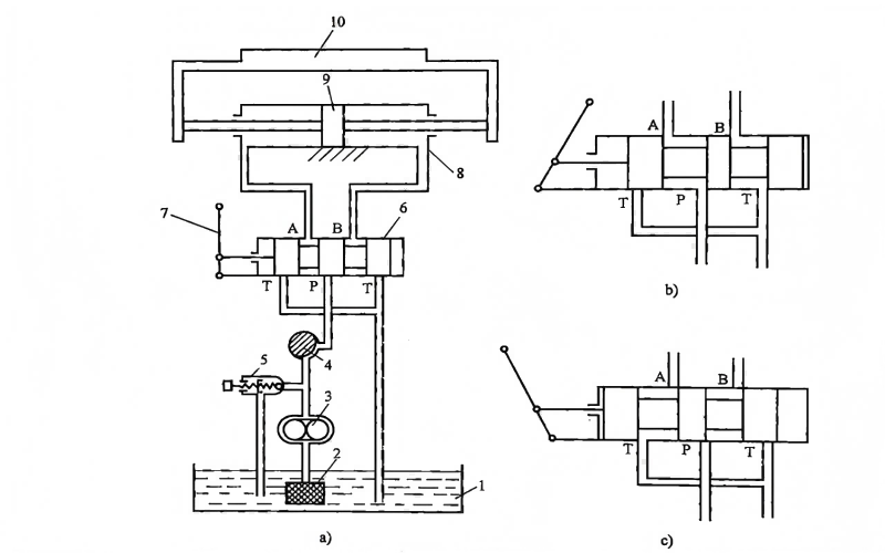
To understand how does a hydrostatic transmission work, let's analyze a simple hydraulic system used to achieve reciprocating motion of a worktable in a machine tool (Figure 1-1). The hydraulic cylinder 8 is fixed to the machine bed, and the piston 9, together with its rod, drives the worktable 10 to perform linear reciprocating motion.
Figure 1-1: Hydraulic Transmission System of a Simple Machine Tool
| Number | Component | Function |
|---|---|---|
| 1 | Oil Tank | Stores hydraulic fluid and acts as a reservoir |
| 2 | Mesh Filter | Filters contaminants from the hydraulic fluid |
| 3 | Hydraulic Pump | Converts mechanical energy to hydraulic energy |
| 4 | Throttle Valve | Controls fluid flow rate to regulate speed |
| 5 | Relief Valve | Controls system pressure and relieves excess fluid |
| 6 | Directional Control Valve | Changes fluid direction to reverse motion |
| 7 | Handle | Manually operates the directional control valve |
| 8 | Hydraulic Cylinder | Converts hydraulic energy to linear mechanical energy |
| 9 | Piston | Moves within cylinder to create mechanical motion |
| 10 | Worktable | Platform moved by the hydraulic system |
An electric motor drives the hydraulic pump 3, which draws oil from the tank 1 through the mesh filter 2. The oil flows through the throttle valve 4 to the directional control valve 6. When the handle 7 is in the position shown in Figure 1-1a, ports P is not connected to A, B, or T, so no oil flows to the hydraulic cylinder 8, and the worktable remains stationary.
To understand how does a hydrostatic transmission work in creating motion, consider when the handle 7 is pushed to the position shown in Figure 1-1b. In this configuration, oil flows from P→A→left chamber of hydraulic cylinder 8; while oil from the right chamber of hydraulic cylinder 8 flows through B→T, causing the worktable 10 to move to the right.
When the handle 7 is pushed to the position shown in Figure 1-1c, the oil flow path changes: oil flows from P→B→right chamber of hydraulic cylinder 8; while oil from the left chamber of hydraulic cylinder 8 flows through A→T, causing the worktable 10 to move to the left. This directional control is a key aspect of how does a hydrostatic transmission work in practical applications.
This example clearly illustrates how the directional control valve 6 changes the path of hydraulic oil, allowing the hydraulic cylinder to reverse direction continuously, thereby achieving reciprocating motion of the worktable. This directional control is fundamental to understanding how does a hydrostatic transmission work in machinery requiring reversible motion.
The speed of the worktable can be adjusted using the throttle valve 4. The throttle valve regulates the flow rate of oil passing through it by changing the size of its opening, which in turn controls the speed of the worktable. Flow control is another critical aspect when exploring how does a hydrostatic transmission work in variable-speed applications.
As the worktable moves, it must overcome various resistances, including cutting forces and frictional forces on the surfaces of moving parts. These resistances are overcome by the pressure of the oil output by the hydraulic pump. Depending on operating conditions, the pressure of the oil output by the hydraulic pump should be adjustable. Additionally, under normal circumstances, the oil discharged by the hydraulic pump is often more than what the hydraulic cylinder requires. The excess oil can flow back to the tank through the relief valve 5. In Figure 1-1, component 2 is a mesh filter that serves to filter the oil. This pressure regulation is essential to understanding how does a hydrostatic transmission work safely under varying loads.
Key Insights from System Analysis
- Hydraulic transmission relies on the pressure energy of moving fluid to transmit power, which differs from "hydraulic power transmission" that relies on the kinetic energy of the fluid. This distinction is crucial when answering how does a hydrostatic transmission work compared to other fluid-based systems.
- When a hydraulic system is operating, the hydraulic pump converts mechanical energy into pressure energy, and the actuator (hydraulic cylinder) converts pressure energy into mechanical energy. This energy conversion process is central to understanding how does a hydrostatic transmission work.
- The oil in a hydraulic transmission system operates under regulated and controlled conditions, making it difficult to separate hydraulic transmission from hydraulic control. This integration is a key characteristic when explaining how does a hydrostatic transmission work in complex machinery.
- A hydraulic transmission system must meet the force and speed requirements of the machine components (worktable) it drives. These performance considerations are vital when evaluating how does a hydrostatic transmission work in specific applications.
- Hydraulic transmission requires a working medium. It uses fluid as the working medium to transmit signals and power. The properties of this medium significantly influence how does a hydrostatic transmission work in different operating environments.
Understanding these principles provides a foundation for answering how does a hydrostatic transmission work in various industrial applications. From simple machine tools to complex construction equipment, the same fundamental principles apply, with variations in scale, pressure, and control mechanisms.
Energy Conversion Process
A key aspect of how does a hydrostatic transmission work is the efficient conversion between mechanical and hydraulic energy. The pump takes mechanical input and creates fluid pressure, while actuators convert this pressure back into mechanical motion with minimal energy loss.
Directional Control Mechanism
Valves play a critical role in answering how does a hydrostatic transmission work for reversible motion. By redirecting fluid flow, these components enable precise control over the direction of hydraulic actuators, essential for many machine operations.
II. Components of a Hydraulic Transmission System
From the example above, we can identify five essential components that answer how does a hydrostatic transmission work as a complete system. Each component plays a vital role in ensuring efficient power transmission, control, and reliability. Together, these components form a cohesive system that can be engineered to meet specific application requirements, whether for high-force industrial presses or precision control in manufacturing equipment. Understanding each part's function is crucial to comprehensively answering how does a hydrostatic transmission work in practical scenarios.
1 Energy Source Devices
These devices convert mechanical energy into hydraulic energy (pressure energy) of the oil. The most common example is the hydraulic pump, which supplies hydraulic oil to the hydraulic system, enabling the entire system to operate.
When exploring how does a hydrostatic transmission work, the pump is often considered the "heart" of the system. There are several types of hydraulic pumps, including gear pumps, vane pumps, and piston pumps, each with its own advantages in terms of pressure capacity, flow rate, and efficiency.
The pump's performance characteristics directly influence the overall system's capabilities, making it a critical component in determining how does a hydrostatic transmission work under specific operating conditions. Proper pump selection based on pressure requirements, flow rate needs, and efficiency considerations is essential for optimal system performance.
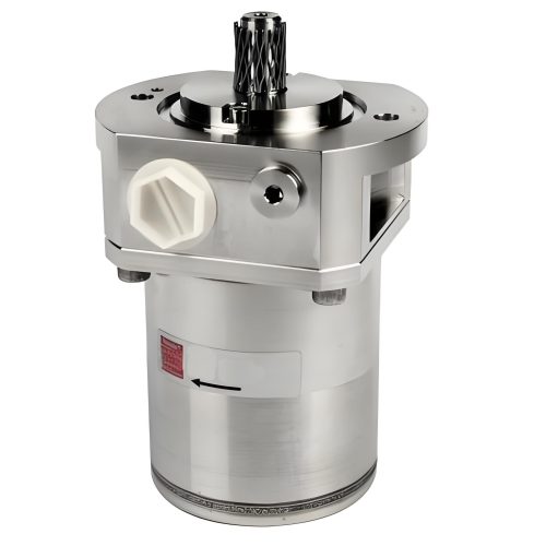
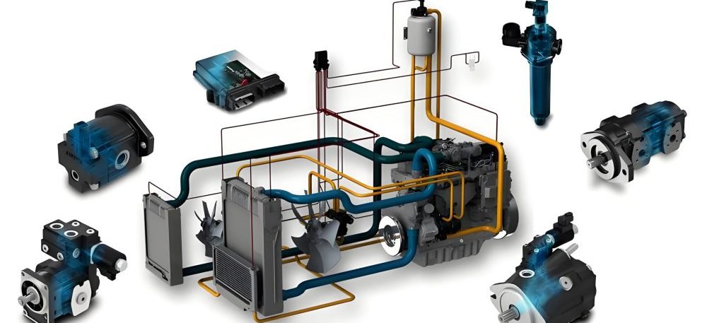
Common types of hydraulic pumps
2 Actuating Devices
Hydraulic cylinders and motors
These devices convert the pressure energy of the oil into mechanical energy and perform work. Examples include hydraulic cylinders, which produce linear motion, and hydraulic motors, which produce rotational motion.
Actuators are the "muscles" of the system when considering how does a hydrostatic transmission work to perform useful work. Hydraulic cylinders come in various designs, including single-acting, double-acting, telescopic, and differential types, each suited for specific applications.
Hydraulic motors, similar in principle to pumps but operating in reverse, provide rotational motion and torque. The selection between cylinders and motors, as well as their specific types, is a key consideration in determining how does a hydrostatic transmission work for a particular mechanical task.
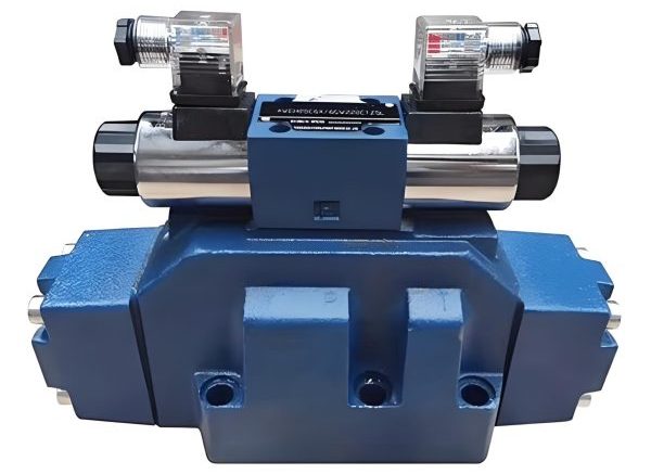
3 Control and Regulation Devices
These devices control the pressure, flow rate, and direction of the oil in the hydraulic system. Components such as the directional control valve, throttle valve, and relief valve in Figure 1-1 all belong to this category of devices.
Control devices are the "brain" that determines how does a hydrostatic transmission work in terms of precision and adaptability. Pressure control valves, including relief valves, pressure reducing valves, and sequence valves, manage system pressure to ensure safe and efficient operation.
Flow control valves, such as throttle valves and flow dividers, regulate the rate of fluid movement, directly controlling actuator speed. Directional control valves manage the path of fluid flow throughout the system.
Modern systems often incorporate sophisticated electronic controls alongside hydraulic valves to create electro-hydraulic systems that offer enhanced precision and programmability. This integration significantly advances how effectively how does a hydrostatic transmission work in automated industrial processes.
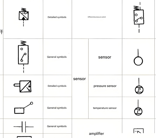
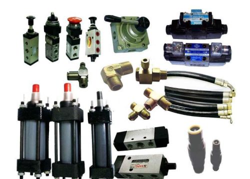
Hydraulic control valves and their symbols
4 Auxiliary Devices
Hydraulic system auxiliary components
These include all devices other than the three categories mentioned above. Examples from Figure 1-1 include the mesh filter and oil pipes. While often overlooked when first learning how does a hydrostatic transmission work, these components play an important role in ensuring the hydraulic system operates reliably, stably, and durably.
Other auxiliary components include reservoirs, pressure gauges, accumulators, seals, fittings, and coolers. Each of these components contributes to the overall performance and longevity of the system.
For example, filters maintain fluid cleanliness, which is critical to preventing component wear and system failure. Coolers regulate fluid temperature, ensuring viscosity remains within optimal ranges. These auxiliary devices might not be the first consideration when exploring how does a hydrostatic transmission work, but they are essential for maintaining system performance over time.
5 Working Medium
The working medium is typically hydraulic oil or other synthetic fluids. This medium is fundamental to understanding how does a hydrostatic transmission work, as it serves as both the energy transfer medium and the lubricant for system components.
The properties of the hydraulic fluid significantly impact system performance. Viscosity, viscosity index, lubricity, thermal stability, and chemical compatibility are all critical characteristics.
Different applications require different types of hydraulic fluids. For example, high-temperature environments may necessitate synthetic fluids, while food processing equipment requires food-grade hydraulic oils. The selection of appropriate working medium directly affects how does a hydrostatic transmission work in terms of efficiency, reliability, and service life. Regular maintenance of the working medium, including filtration and periodic replacement, is essential for system health.
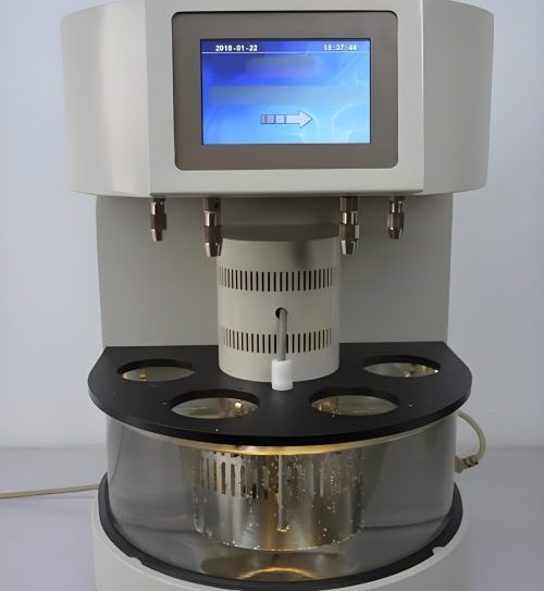
Hydraulic fluids and testing equipment
Hydraulic System Component Integration
Understanding how these components work together is essential to fully answering how does a hydrostatic transmission work as a complete system. Each part depends on the others to create an efficient, reliable power transmission solution that offers advantages in terms of power density, control precision, and versatility.
Advantages and Applications
Now that we understand how does a hydrostatic transmission work and its component parts, it's important to recognize why this technology is so widely used across industries. Hydraulic systems offer numerous advantages that make them suitable for a wide range of applications.
Key Advantages
- High power density, providing significant force and torque in compact designs
- Precise control over speed, force, and position
- Smooth operation with minimal vibration
- Overload protection through pressure relief mechanisms
- Ability to transmit power over long distances with flexible hoses
- Easy integration with electronic controls for automation
Common Applications
- Manufacturing machinery and production lines
- Construction equipment (excavators, cranes, loaders)
- Marine systems and offshore equipment
- Automotive manufacturing and testing equipment
- Aerospace and defense systems
- Agricultural machinery and irrigation systems
These advantages explain why understanding how does a hydrostatic transmission work is valuable across so many engineering disciplines. As technology advances, hydraulic systems continue to evolve, incorporating smarter controls and more efficient components while maintaining the fundamental principles that make them so effective.
Conclusion
Hydraulic transmission systems represent a sophisticated integration of mechanical and fluid power principles. By understanding the components and operational principles outlined here, you now have a solid foundation for answering how does a hydrostatic transmission work in various industrial contexts. From simple machine tools to complex heavy machinery, these systems continue to be indispensable in modern engineering due to their unique combination of power, precision, and versatility.