Electro-Hydraulic Servo Valve Technology
The electro-hydraulic servo valve is a sophisticated multi-stage servo element that bridges electrical and hydraulic control systems. It excels at amplifying weak electrical input signals into powerful hydraulic energy outputs, making it an indispensable component in precision control applications.
High Precision Control
Exceptional accuracy in flow and pressure regulation
High Gain Amplification
Significant power amplification from input to output
Fast Response
Rapid reaction to input signal changes
Introduction to Electro-Hydraulic Servo Valves
An electro-hydraulic servo valve represents the pinnacle of precision control technology, seamlessly integrating electrical and hydraulic systems to deliver exceptional performance. This advanced component serves as a critical interface between electronic control systems and hydraulic actuation, enabling precise regulation of fluid power in a wide range of industrial applications.
The fundamental principle behind electro-hydraulic servo valves lies in their ability to convert low-power electrical signals into high-power hydraulic outputs. This conversion process is achieved through a sophisticated combination of electromagnetic and hydraulic components working in harmony. The result is a device capable of responding with remarkable speed and accuracy to control signals, making it ideal for applications requiring precise positioning, velocity control, or force regulation.
One of the key advantages of electro-hydraulic servo valves is their exceptional control precision. This precision is maintained across a wide range of operating conditions, ensuring consistent performance even in demanding environments. Additionally, these valves offer high amplification ratios, meaning even minute electrical signals can be translated into significant hydraulic power outputs.
The versatility of electro-hydraulic servo valves has led to their widespread adoption across various industries, including aerospace, automotive manufacturing, power generation, and industrial automation. In each of these sectors, the ability to precisely control hydraulic systems is critical to achieving optimal performance, efficiency, and safety.
Key Advantages
- Exceptional control precision
- High power amplification
- Rapid response characteristics
- Wide operating range
- Excellent linearity and repeatability
Typical Applications
- Aerospace flight control systems
- Industrial robotics and automation
- Material testing machines
- Precision manufacturing equipment
- Power generation turbine control
Performance Metrics
- Flow capacity: 0.5 to 500 l/min
- Operating pressure: up to 350 bar
- Response time: less than 10 ms
- Control resolution: 0.1% of full scale
- Dynamic range: 1000:1 turndown ratio
Structure and Working Principle
Component Navigation
- Overall Structure
- Torque Motor
- Hydraulic Amplifier
- Nozzle-Flapper Stage
- Spool Valve Stage
- Feedback Mechanism
Interactive Diagram
Click on components in the diagram to learn more about their function.
Overall Structure
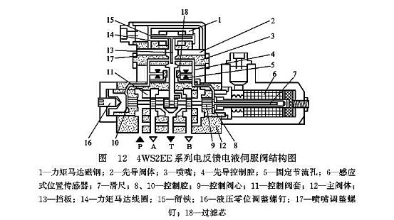
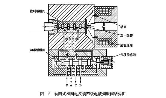
A typical electro-hydraulic servo valve consists of two main sections: an electromagnetic section and a hydraulic section. The electromagnetic section functions as a torque motor, while the hydraulic section operates as a two-stage hydraulic amplifier. This combination allows for precise control and efficient power amplification.
The hydraulic amplifier is divided into two stages: a double nozzle-flapper valve as the first stage (前置放大级) and a four-way spool valve as the second stage (功率放大级). This two-stage design provides the necessary amplification to convert the small force from the torque motor into a powerful hydraulic output capable of controlling large actuators.
Key Components Overview
Torque Motor
Converts electrical signals to mechanical torque
Nozzle-Flapper
First stage hydraulic amplifier
Spool Valve
Second stage power amplifier
Feedback Mechanism
Provides stability and accuracy
Torque Motor
The torque motor is the electromagnetic component that serves as the input stage of the servo valve. It consists of a pair of permanent magnets, pole pieces, an armature, a control coil, and a flexure tube that supports the armature and flapper assembly.
The permanent magnets magnetize the upper and lower pole pieces to form a fixed magnetic field with north (N) and south (S) poles. The armature is connected to the flapper and supported by the flexure tube, which is fixed to the valve body, positioning it between the upper and lower pole pieces. The lower end of the flapper has a ball joint that fits into a groove in the center of the spool valve.
When no current passes through the coil, the torque motor produces no output torque, and the flapper remains centered between the two nozzles. When an input signal current passes through the coil, the armature becomes magnetized. If the current causes the left end of the armature to become an N pole and the right end to become an S pole, the armature rotates counterclockwise according to the principle of同性相斥、异性相吸 (like poles repel, opposite poles attract). This rotation causes the flexure tube to bend, generating a corresponding counter torque that stops the armature rotation at a specific angle θ. The magnitude of this angle is directly proportional to the input current, effectively converting the electrical signal into a mechanical displacement.
Torque Motor Components
- Permanent Magnets: Create a fixed magnetic field
- Pole Pieces: Concentrate magnetic flux
- Armature: Rotates in response to coil current
- Control Coil: Receives electrical input signal
- Flexure Tube: Provides torsional spring action
Performance Characteristics
- Linear Response: Displacement proportional to input current
- Low Hysteresis: Minimal difference between increasing and decreasing signals
- High Sensitivity: Responds to very small input signals
- Fast Response: Rapidly reacts to signal changes
- Stable Operation: Consistent performance over time
Hydraulic Amplifier
The torque motor produces only a small amount of torque, insufficient to directly operate the spool valve and generate the required hydraulic power. Therefore, a two-stage amplification process is implemented in the hydraulic amplifier: a pilot stage and a power stage.
This two-stage design is crucial for achieving both high sensitivity and high power capacity in the servo valve. The first stage (pilot stage) provides the necessary sensitivity to respond to small input signals, while the second stage (power stage) provides the flow capacity and pressure rating required for practical applications.
Amplification Stages Comparison
| Characteristic | Pilot Stage (Nozzle-Flapper) | Power Stage (Spool Valve) |
|---|---|---|
| Primary Function | Convert mechanical displacement to pressure difference | Convert pressure difference to high flow rate |
| Flow Capacity | Low (typically <1 l/min) | High (up to 500 l/min) |
| Pressure Rating | High (up to 350 bar) | High (up to 350 bar) |
| Response Time | Very fast (1-2 ms) | Fast (5-10 ms) |
| Sensitivity | Very high | Moderate |
| Power Handling | Low | High |
Nozzle-Flapper Stage (Pilot Stage)
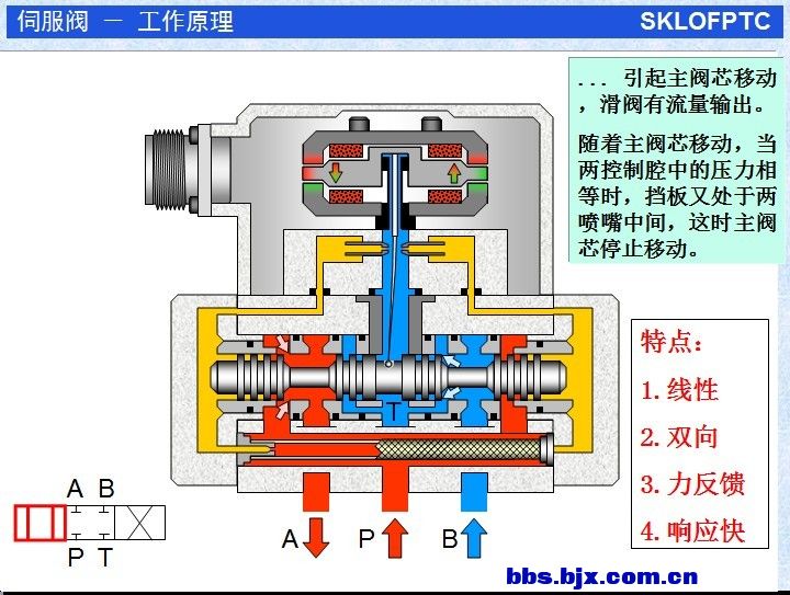
The pilot stage is a double nozzle-flapper valve, consisting primarily of the flapper, two nozzles, fixed orifices, and filters. Hydraulic fluid flows through the filters and two fixed orifices to the left and right end chambers of the spool valve and to the two nozzle chambers. From the nozzles, the fluid sprays out and flows back to the tank through the central chamber of the spool valve.
When there is no output signal from the torque motor, the flapper remains stationary, and the pressures in the left and right chambers are equal, keeping the spool valve also stationary. However, when the torque motor has a signal output causing the flapper to deflect, the clearance between the nozzles and the flapper changes asymmetrically. This change in clearance creates a pressure difference between the two sides, which drives the spool to move.
The nozzle-flapper stage is highly sensitive to small displacements of the flapper, making it ideal for converting the small mechanical motion from the torque motor into a usable hydraulic signal. The relationship between flapper displacement and pressure difference is highly linear, contributing to the overall precision of the servo valve.
Nozzle-Flapper Operation
Without Input Signal:
- Flapper is centered between nozzles
- Equal clearance on both sides
- Equal fluid flow from both nozzles
- Equal pressure in both spool end chambers
- Spool remains in neutral position
With Input Signal:
- Flapper deflects towards one nozzle
- Reduced clearance on one side, increased on the other
- Reduced flow from one nozzle, increased from the other
- Pressure increases on side with reduced flow
- Pressure difference moves spool valve
Spool Valve Stage (Power Stage)
The power amplification stage primarily consists of the spool valve and the feedback spring plate at the lower part of the flapper. When the pilot stage outputs a pressure difference signal, the spool valve moves, connecting the main hydraulic power circuit (as shown in the lower port oil flow in Figure 10-10). Since the opening of the spool valve after displacement is proportional to the input current of the torque motor, the output flow of the valve is also proportional to the input current. When the input current reverses, the output flow also reverses.
The spool valve is typically a four-way design, meaning it has four main ports: pressure (P), tank (T), and two work ports (A and B). As the spool moves, it opens or closes passages between these ports, controlling the flow rate and direction of fluid to the actuator.
The design of the spool valve is critical to the overall performance of the servo valve. The spool and valve body are manufactured with extremely tight tolerances to minimize leakage and ensure precise control. The spool lands (the cylindrical sections of the spool) are carefully designed to provide the desired flow characteristics, typically a linear relationship between spool displacement and flow rate.
Transmission Oil vs Fluid Considerations
The selection of appropriate hydraulic fluid is crucial for the optimal performance of electro-hydraulic servo valves. While the terms "transmission oil" and "hydraulic fluid" are sometimes used interchangeably, there are important differences to consider:
Transmission Oil Characteristics:
- Designed primarily for power transmission
- Typically contains friction modifiers
- May have different viscosity-temperature properties
- Often optimized for specific transmission designs
Hydraulic Fluid Characteristics:
- Engineered for hydraulic power systems
- Optimized for wear protection in valves and pumps
- Controlled compressibility for precise control
- Enhanced oxidation and thermal stability
For electro-hydraulic servo valves, the use of high-quality hydraulic fluid specifically formulated for servo applications is recommended. These fluids provide the necessary viscosity characteristics, wear protection, and oxidation resistance to ensure long service life and consistent performance. While transmission oil may work in some hydraulic systems, it may not provide the same level of performance and protection in precision servo valve applications.
Feedback Mechanism
As the spool valve moves, the small ball at the lower end of the flapper also moves with it, causing the flapper spring plate to generate an elastic counterforce that prevents further movement of the spool. On the other hand, the deformation of the flapper reduces its displacement between the two nozzles, thereby achieving feedback. When the hydraulic force on the spool balances with the elastic counterforce of the flapper, the spool maintains this opening and no longer moves. Since this final position is balanced through the feedback effect of the flapper's elastic counterforce, this feedback is referred to as force feedback.
The feedback mechanism is essential for the stability and accuracy of the servo valve. Without feedback, the valve would be unstable and unable to maintain precise control. The force feedback system creates a closed-loop control system within the valve itself, ensuring that the spool position accurately corresponds to the input signal.
The stiffness of the feedback spring and the geometry of the feedback mechanism determine the overall gain and response characteristics of the servo valve. These parameters are carefully designed to achieve the desired performance characteristics for specific applications.
Feedback System Benefits
Improved Stability
Prevents oscillations and hunting
Enhanced Accuracy
Precise positioning of spool valve
Consistent Performance
Minimizes effects of temperature and wear
Performance Characteristics
Flow Characteristics
The flow characteristic of an electro-hydraulic servo valve describes the relationship between the input current and the output flow rate. This relationship is typically very linear, which is crucial for precise control applications. The flow rate is also affected by the pressure drop across the valve, following the square root relationship described by the orifice equation.
Key Flow Parameters
- Flow Gain (Kq): The ratio of flow rate to input current (l/min per mA)
- Pressure Gain (Kp): The ratio of pressure drop to input current (bar per mA)
- Flow-Pressure Coefficient (Kc): The ratio of flow rate to pressure drop (l/min per bar)
Dynamic Response
The dynamic response of a servo valve is a critical performance parameter, particularly in applications requiring rapid and precise control. It is typically characterized by parameters such as response time, frequency response, and phase shift.
Key Dynamic Parameters
- Response Time: Time to reach 90% of final value (typically 5-10 ms)
- Bandwidth: Frequency at which response is reduced by 3 dB (typically 100-500 Hz)
- Phase Shift: Time delay between input signal and output response
Transmission Oil vs Fluid Performance Impact
The choice between transmission oil and hydraulic fluid can significantly impact the performance and service life of electro-hydraulic servo valves. While both fluids serve to transmit power, their formulations are optimized for different purposes, leading to differences in performance characteristics.
| Performance Aspect | Hydraulic Fluid | Transmission Oil | Impact on Servo Valve |
|---|---|---|---|
| Viscosity Stability | Excellent | Good | Hydraulic fluid maintains consistent viscosity across temperature ranges, ensuring stable valve performance |
| Wear Protection | Optimized for hydraulic components | Formulated for gears and clutches | Hydraulic fluid provides superior protection for valve spools and precision components |
| Oxidation Resistance | High | Moderate | Hydraulic fluid resists sludge formation, extending maintenance intervals |
| Foaming Tendency | Low | Higher | Hydraulic fluid minimizes cavitation and maintains consistent performance |
| Filterability | Excellent | Good | Hydraulic fluid maintains cleanliness, critical for servo valve precision |
| Temperature Range | Wide | Moderate | Hydraulic fluid performs reliably in extreme operating conditions |
Recommendation
For optimal performance and longevity of electro-hydraulic servo valves, it is strongly recommended to use high-quality hydraulic fluid specifically formulated for servo applications. While transmission oil may be suitable for some hydraulic systems, it lacks the specialized additives and properties required to maintain the precision and reliability of servo valves over extended periods of operation. The use of proper hydraulic fluid will ensure consistent performance, reduce maintenance requirements, and extend the service life of the valve.
Applications of Electro-Hydraulic Servo Valves
Electro-hydraulic servo valves are used in a wide range of industrial applications where precise control of hydraulic power is required. Their ability to provide accurate, fast, and reliable control makes them ideal for applications demanding high performance and precision.
Aerospace
In aerospace applications, servo valves control flight surfaces, landing gear, and engine components. They provide the precision and reliability required for safe operation in extreme conditions.
- Flight control systems
- Landing gear actuation
- Engine thrust vector control
- Variable geometry engine components
Industrial Automation
In industrial settings, servo valves are used in robotics, material handling, and automated production lines. They provide precise control for manufacturing processes requiring high accuracy.
- Robotic arms and manipulators
- Automated assembly equipment
- Material testing machines
- Precision grinding and milling machines
Power Generation
In power plants, servo valves control turbine governors, boiler controls, and other critical systems. They help maintain stable operation and efficient power generation.
- Steam and gas turbine control
- Generator excitation systems
- Boiler feedwater control
- Dam gate positioning
Application-Specific Considerations
Transmission Oil vs Fluid in Mobile Applications
In mobile hydraulic systems, such as those found in construction equipment and agricultural machinery, there is often a trend toward using a single fluid for both hydraulic systems and transmissions. While this approach simplifies maintenance and reduces inventory costs, it can present challenges for systems incorporating servo valves.
Transmission fluids are formulated with different additives than hydraulic fluids, including friction modifiers that can affect the performance of servo valves. In applications where precise control is critical, dedicated hydraulic fluid is still recommended for servo valve circuits, even if other parts of the system use transmission oil.
Servo Valve Sizing Considerations
Proper sizing of servo valves is crucial for optimal performance. The valve must be sized to provide the required flow rate at the system pressure while maintaining the necessary response characteristics.
Oversized valves can lead to reduced precision and increased energy consumption, while undersized valves may not provide sufficient flow for the application. The selection process should consider not only steady-state flow requirements but also dynamic response characteristics and system stability.
Maintenance and Troubleshooting
Preventive Maintenance
Proper maintenance is essential for ensuring the long-term performance and reliability of electro-hydraulic servo valves. Regular maintenance procedures help prevent unexpected failures and ensure consistent performance.
Recommended Maintenance Schedule
-
Daily: Check fluid level and temperature
-
Weekly: Inspect for leaks and abnormal noises
-
Monthly: Check fluid contamination levels
-
Quarterly: Replace filters and sample fluid
-
Annually: Complete system inspection and fluid analysis
Fluid Maintenance
Maintaining clean, high-quality hydraulic fluid is critical for servo valve performance. Contaminants such as particles, water, and air can significantly impact valve performance and寿命.
- Maintain fluid cleanliness to ISO 4406 Class 16/13 or better
- Monitor and control fluid temperature (ideally 40-50°C)
- Check for water contamination regularly
- Use only recommended fluid types
- Implement proper fluid storage and handling procedures
Troubleshooting Common Issues
Despite proper maintenance, issues may occasionally arise with electro-hydraulic servo valves. Understanding common problems and their solutions can help minimize downtime and restore system performance quickly.
Common Problems and Solutions
Slow Response
Possible Causes:
- Fluid viscosity too high
- Contaminated fluid
- Restricted supply line
- Worn valve components
Recommended Actions:
- Check fluid temperature and viscosity
- Analyze fluid for contamination
- Inspect supply line for restrictions
- Consider valve overhaul or replacement
Hunting or Instability
Possible Causes:
- System gain too high
- Feedback mechanism issues
- Fluid contamination
- Air in hydraulic system
Recommended Actions:
- Adjust system gain
- Inspect feedback mechanism
- Bleed air from system
- Check fluid for contamination
Leakage
Possible Causes:
- Worn seals or gaskets
- Damaged valve body
- Excessive operating pressure
- Improper installation
Recommended Actions:
- Replace worn seals and gaskets
- Inspect valve body for damage
- Verify system pressure is within specifications
- Check installation torque on flange bolts
Transmission Oil vs Fluid in Maintenance
The choice between transmission oil and hydraulic fluid has significant implications for maintenance practices and intervals. Understanding these differences can help develop appropriate maintenance schedules and procedures.
Hydraulic Fluid Maintenance
- Longer service life (typically 5000-10000 operating hours)
- Better resistance to oxidation and thermal breakdown
- Superior filterability, maintaining system cleanliness
- More stable viscosity across temperature ranges
- Typically lower maintenance costs over time
Transmission Oil Maintenance
- Shorter service life (typically 2000-5000 operating hours)
- Greater tendency to form sludge and deposits
- May require more frequent filter changes
- Additive package may deplete more quickly in hydraulic service
- Potentially higher long-term maintenance costs
Conclusion
Electro-hydraulic servo valves represent a critical technology in modern control systems, providing the essential interface between electronic control and hydraulic power. Their unique combination of precision, power, and responsiveness makes them indispensable in a wide range of industrial applications, from aerospace and defense to manufacturing and power generation.
The sophisticated design of these valves, incorporating electromagnetic torque motors, two-stage hydraulic amplification, and precise feedback mechanisms, enables them to convert weak electrical signals into powerful hydraulic outputs with exceptional accuracy and repeatability. This performance is achieved through the careful integration of mechanical, electrical, and hydraulic technologies, each contributing to the overall functionality of the valve.
Proper selection and maintenance of hydraulic fluid are crucial for ensuring optimal performance and longevity of servo valves. While transmission oil may be suitable for some hydraulic systems, dedicated hydraulic fluid specifically formulated for servo applications is recommended to maintain the precision and reliability required in critical applications.
As technology continues to advance, electro-hydraulic servo valves are evolving to meet the increasing demands for higher performance, greater efficiency, and improved reliability. These advancements, combined with proper application engineering and maintenance practices, will ensure that servo valves remain a vital component in precision control systems for years to come.
Understanding the principles of operation, performance characteristics, and maintenance requirements of electro-hydraulic servo valves is essential for engineers and technicians working with hydraulic control systems. By leveraging this knowledge, they can optimize system design, troubleshoot issues effectively, and ensure the reliable operation of critical equipment.